
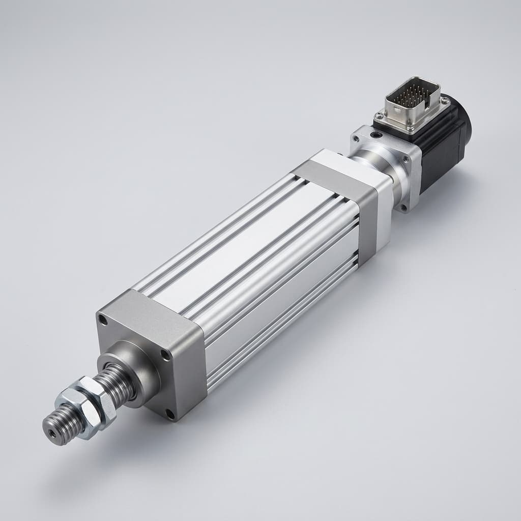
Radial Load Isolation and Moment Decoupling in Inverted Roller Screw Actuators: Permissible Side-Load Limits, External Guidance Sizing, and Articulated Mounting Architecture
Size inverted roller screw side-load isolation with guide reaction examples, mounting checks and supplier-specific limits. Prepare your actuator RFQ checklist.
Inverted roller screw side-load limits are specific to the complete actuator, its extension and its supports. An axial dynamic rating does not establish an allowable radial force. Design the load path so external guides or an appropriate pivot arrangement carry lateral forces and overturning moments; obtain written supplier limits before relying on an internal guide bushing.
Inverted planetary roller screws use threaded rollers between a screw and an internally threaded nut to transmit axial force in a compact package. Their axial load-sharing capability makes them useful in electromechanical actuators, but it does not qualify the screw assembly as a linear guide. The screw, thrust bearings, push tube, housing and bushings each have separate structural limits.
This guide helps mechanical engineers, robotics hardware leads and OEM buyers choose between internal guidance, external rails and articulated mounting. It provides a load-path comparison, reproducible statics examples, alignment checks and an RFQ checklist. It does not provide a universal side-load percentage or certify a particular actuator.
Published and content reviewed: November 5, 2026. Scope: global OEM actuator selection, in SI metric units. Calculations below are hypothetical engineering screening examples, not measured product performance. Applicable limits depend on screw geometry, stroke, supports, lubrication, temperature and the complete duty cycle. Manufacturer application approval remains necessary for the selected assembly.
Preparing an integration review? Submit your CAD geometry and load vectors, including extension, load application points and duty cycle, to discuss mounting feasibility and the evidence needed for an actuator quotation.
1. Contact Mechanics: Why Radial Loads Need a Separate Load Path
A side load can bend the extending member and redistribute contact forces inside an actuator. The following schematic illustrates possible mechanisms; their severity depends on construction and operating conditions.
Thread Contact and Uneven Load Distribution
Even under axial loading, the forces on individual rollers and thread turns need not be identical. Geometry, elastic deformation, preload and manufacturing variation affect load sharing. Bending can further concentrate contact near thread edges, increase local stress and shorten useful life.
A contact-stress value cannot be calculated from total axial force alone. It also requires the load at the individual contact, local curvature, material properties and the actual contact geometry. This guide therefore provides no universal Hertzian stress threshold, steel yield limit or percentage of axial rating at which damage begins. Ask the screw supplier to assess the combined load case rather than applying a simplified line-contact equation to the whole assembly.
Roller Alignment and Synchronizing Features
Some planetary roller screw designs use synchronizing gears or related features to control roller motion. Misalignment can disturb their intended engagement and increase wear. The arrangement and rotating members vary between designs, so a diagram of one arrangement cannot establish a failure sequence for every inverted screw.
Unexpected vibration, increased running torque or metallic debris warrants investigation. These observations can have several causes, including lubrication, contamination and bearing problems; they do not identify side loading by themselves. Avoid predicting tooth failure within a fixed number of revolutions without inspection or test evidence.
Lubrication and Rod Seals
Off-axis loading can change local sliding, lubricant film conditions and friction. Film thickness depends on speed, viscosity, temperature, roughness and contact pressure. Neither a guaranteed flash temperature nor an immediate transition to boundary lubrication follows from a specified side-load percentage.
Rod displacement can also load one side of a wiper more heavily while opening a contamination path on the other. Select sealing and lubrication provisions for the environment, then confirm that the mechanical guidance controls deflection. Adding a scraper cannot correct an unsuitable load path or make an unrated radial load acceptable.
2. Establishing Permissible Side-Load Limits
There Is No Universal Percentage of Axial Capacity
A statement such as “side load below 1% of dynamic axial capacity is safe” is not an acceptance criterion. Axial dynamic capacity describes a defined axial fatigue-rating basis. It does not encode the bushing span, rod overhang, lateral stiffness or moment capacity of a finished actuator.
For an unguided screw component, plan to keep radial forces and bending moments out of the screw load path unless the supplier explicitly approves them. For an enclosed electric cylinder, request a radial-force-versus-extension curve and any combined axial/radial/moment restrictions. Identify the force application point and whether the stated limit is static, moving, continuous or intermittent. An anti-rotation feature is not automatically a rated payload guide.
If the supplier supplies only an axial rating, record radial capability as unconfirmed. Do not convert the missing data into an allowable force. Either provide external guidance or obtain an application-specific assessment covering the actual mechanism.
A Reproducible Cantilever Moment Example
Screening example: For a transverse force at the rod-end pin, the moment about the front support is M = Fr × (L0 + s), where L0 is the retracted support-to-pin overhang and s is the extension. This is a free-body calculation, not an internal bushing rating.
Assume Fr = 400 N, L0 = 0.050 m and s = 0.300 m. Then M = 400 × 0.350 = 140 N·m. At zero extension, the same force produces 20 N·m. Stating the initial overhang matters: using the extension alone would give 120 N·m at full stroke and omit part of the load case.
For an idealized pair of lateral supports separated by b = 0.080 m, the reaction couple needed to resist that moment has magnitude M / b = 1,750 N. The direct transverse force must also satisfy force equilibrium. Actual support reactions require the real support locations and stiffness; the screw nut must not be assumed to provide the second guide bearing without supplier approval.
Axial Fatigue Life Has a Defined Boundary
ISO 3408-5:2006 addresses ball-screw axial load ratings and life. It is not a roller-screw side-load standard. For a roller screw, use the manufacturer's rating definitions and calculation method for that product.
Where that method specifies the cubic axial relationship, a basic rating-life expression may take the form L10 = (Ca / Fm)^3 × 10^6 revolutions. Use only compatible definitions of dynamic capacity Ca and equivalent axial load Fm. Converting revolutions to hours additionally requires the motion profile, lead and operating time.
An axial fatigue calculation does not independently check radial loading, lubrication, contamination, buckling or thrust-bearing limits. This article supplies no universal percentage reduction in life under side loading. Keep the axial life estimate and structural load-path approval as separate RFQ deliverables.
3. Engineering Comparison: Internal Bushings, External Guidance and Articulated Mounts
The six architectures below solve different load-path problems. Their capacities cannot be expressed as interchangeable percentages of screw axial rating. Compare complete assemblies and include mounting surfaces, couplers, brackets and installation effort in the quotation.
| Architecture | Intended load path | Capacity evidence to request | Alignment concern | Packaging and procurement consequence | Suitable screening use |
|---|---|---|---|---|---|
| Standard internal bushing | Housing nose supports the moving rod | Supplier radial-force curve at the actual extension and axial load | Rod deflection and bushing clearance | Compact package; verify that guidance is rated, not merely present | Primarily axial motion with approved parasitic lateral force |
| Extended or dual internal bushings | Spaced supports react lateral force and moment through the housing | Bushing span, wear assumptions and combined-load envelope | Housing stiffness and clearance over life | Longer nose or housing; quote the specific option | Restricted external space with documented guidance capacity |
| Single external profile rail | Carriage and rail carry payload lateral loads and moments | Block force/moment ratings, spacing and calculated life | Rail reference surface and actuator coupling | Smaller footprint; a single block may limit moment resistance | Transfer axes where the selected rail arrangement is adequate |
| Dual rails with four blocks | Machine frame receives lateral forces through the guided table | Load distribution, static margins, life and frame stiffness | Parallelism, preload and assembly distortion | Larger footprint and more installation work | Overhung payloads or substantial process moments |
| Spherical rod end plus rear pivot | Ideally, actuator transmits force between pivot centers | Joint, pin, bracket and actuator ratings over the full motion arc | Out-of-plane motion and available swivel | Requires sweep clearance and an independent payload constraint | Linkages that permit an approximately axial actuator load path |
| Intermediate trunnion | Body pivots at approved trunnion supports | Housing clamp approval, pin/bracket loads and buckling assessment | Pivot-axis alignment and rod-end articulation | Specialized housing support and mounting brackets | Pivoting mechanisms where a reviewed trunnion position helps integration |
An articulated actuator does not provide lateral guidance to a free payload. Conversely, external rails do not automatically eliminate screw side load: their geometry and the actuator connection must allow compatible motion. Select the architecture from the free-body diagram before comparing prices.
4. Sizing and Integrating External Profile Rail Guides
Prevent Over-Constraint at the Actuator Connection
A rigid actuator flange, rigid rod-to-carriage attachment and separate guide rails can form competing motion constraints. Small alignment errors then create parasitic forces. A floating alignment joint or a suitable pivot arrangement can reduce those forces, provided it accommodates the required translations and rotations.
Specify a coupler by axial tension/compression capacity, radial float, angular travel, axial compliance, backlash and fatigue conditions. A spherical joint accommodates rotation but does not necessarily allow lateral translation. Floating-joint travel and stiffness are product-specific; neither unlimited float nor perfect axial rigidity should be assumed.
A pivot-mounted actuator also needs the right degrees of freedom at both ends. A single-plane clevis cannot relieve arbitrary out-of-plane error. Account for actuator weight, cable drag, hose forces and friction, because these prevent a real installation from behaving as an ideal two-force member.
Resolve Forces and Moments with Consistent Signs
Define x along travel and use a right-handed coordinate system. For an applied force F at position r relative to the guide reference, use M = r × F:
Mx = y Fz - z Fy
My = z Fx - x Fz
Mz = x Fy - y Fx
Sum contributions from gravity, acceleration, process loads and the drive-force application point for every relevant operating state. Opposing moments can cancel in one state and reinforce in another. An unsigned sum of absolute terms can be a deliberate conservative envelope, but it is not the signed vector equation.
Worked Guide-Reaction Screening Example
Assume a rigid carriage supported by two identical lateral support stations separated along x by d = 0.200 m. A hypothetical Fy = 600 N lateral force acts at x = 0.150 m from the midpoint. Ignore other loads for this one-plane calculation.
The yaw moment is Mz = 600 × 0.150 = 90 N·m. The required moment couple is Mz / d = 450 N. Combining that couple with the direct force gives station demand magnitudes with signs: P1 = 600 / 2 + 450 = 750 N and P2 = 600 / 2 - 450 = -150 N. The guide reactions act opposite these demands. The negative sign indicates a reversed reaction at the second station; it must not be discarded or replaced with zero.
Increasing the station spacing to 0.300 m, while retaining the same force position, reduces the couple component to 300 N, giving demands of 600 N and 0 N for this idealized load case. This comparison explains why block spacing can matter as much as selecting a larger rail. It does not qualify either arrangement for service.
For two rails and four blocks, repeat the assessment for roll, pitch, yaw and direct forces using the guide manufacturer's load-distribution method. Equal load sharing is an assumption that frame compliance and preload can invalidate. Check peak static demand against static ratings and the duty spectrum against dynamic life calculations. Static moment ratings are not dynamic fatigue ratings, and the required safety factor depends on the manufacturer, shock conditions and consequence of failure.
If block reactions are unacceptable, change spacing, rail separation, process-force height or drive-force position before simply increasing actuator thrust. Send a load-case sketch with your RFQ so guide selection and actuator selection use the same reference points.
5. Articulated Mounting Standards: ISO 12240-4 and ISO 15552
Standards help define interfaces; they do not replace component load ratings. ISO 12240-4 concerns spherical plain bearing rod ends. ISO 15552 concerns pneumatic cylinders with detachable mountings in the 1,000 kPa (10 bar) series. Using related mounting geometry on an electric actuator does not establish electric-actuator force capacity, interchangeability or compliance with every provision of the pneumatic standard.
Spherical Rod Ends: Select the Actual Part
A spherical rod end accommodates angular motion within its catalog limits. Available swivel depends on bearing geometry, pin or spacer interference, bracket clearance and load direction. Friction and limited travel mean it cannot guarantee zero transmitted moment in every installation.
Do not select a rod end solely because its dimensional series is described as E or K. Obtain the selected manufacturer's series definition, static and dynamic ratings, thread strength, housing limits and permissible oscillation conditions. A dimensional designation alone does not establish a universal heavy-duty or light-duty class.
For reversing loads, review fatigue, clearance growth, lubrication or liner wear, thread engagement and retention of the locking arrangement. The load through the actuator may be radial to the rod-end bearing bore; resolve bearing loads in the component's own coordinate system. Check pin bending and bracket deflection as well as nominal joint capacity. A maintenance-free liner still has environmental and wear limits.
Rear Clevis or Intermediate Trunnion?
Choose between rear and intermediate pivots by motion envelope, housing support, load path and buckling assessment. Stroke alone does not establish a universal threshold at which a trunnion becomes necessary. A trunnion must attach at a location approved for the actuator housing; an arbitrary clamp can distort the body or interfere with internal components.
The ideal Euler relation is Fcrit = π² E I / (K L)², where E is elastic modulus, I is section second moment, L is the relevant unsupported length and K represents end restraint. For an ideal member with unchanged material, section and end conditions, halving its effective length increases critical load by a factor of four: a 300% increase. Moving a pivot on an assembled actuator does not prove that this member's effective length has halved.
The extended rod, screw, tube and housing may have different sections and boundary conditions. Use the manufacturer's buckling model and required safety margin at maximum compression and extension. Include actuator self-weight, pivot friction and any lateral process load in the structural review. Neither a center-of-gravity location nor a mounting code guarantees a particular capacity improvement.
6. GD&T and the Alignment Budget
Use supplier-approved alignment limits. There is no universal angular or parallelism tolerance for every inverted roller screw actuator. Translate the selected guide, actuator and coupler requirements into one assembly drawing and an inspection procedure.
Relate Angular Error to Travel
For small angles, transverse mismatch is approximately δ = L × θ, with θ in radians. As an illustration, 0.030° = 0.000524 rad; over 500 mm, it produces approximately 0.262 mm of mismatch. An offset change of 0.030 mm over that same travel instead corresponds to approximately 0.00344°. These two requirements are not equivalent.
Allocate allowable mismatch among initial offset, angular error, rail straightness, thermal movement and elastic deflection. Check each contribution against the selected coupler's usable float and angular travel at operating load. A coupler with nominal clearance can still bottom out at one stroke end if the initial offset consumes its travel.
Define Datums and Inspection Conditions
Use the machine's guide reference surfaces and travel direction as explicit assembly datums. Specify rail mounting-face flatness, rail parallelism, actuator pilot location and flange orientation relative to those datums. The values must come from the actual component requirements and the functional error budget; do not copy numerical tolerances from an unrelated actuator.
Record where and how each feature is measured. Face runout measured during rotation, surface perpendicularity and centerline parallelism are different controls. A total indicator reading without a reference axis, measurement radius or setup does not completely define a GD&T requirement.
During commissioning, record rail alignment and rod-to-carriage offset through travel before tightening the final connection. Repeat the agreed checks after tightening and, where relevant, at operating temperature. A common machined base can simplify alignment, but single-setup machining is not the only acceptable manufacturing method if the assembled geometry is verified.
7. Procurement and Engineering Verification Checklist
Use this checklist to make supplier answers comparable. Unconfirmed structural limits remain open engineering items; they should not silently become procurement assumptions.
- Force vectors: Supply axial and radial forces, three-axis moments, application points and coordinate definitions for normal motion, gravity, process loading and emergency deceleration.
- Radial capability: Obtain the selected actuator's allowable radial force versus extension, force application point and combined-load restrictions. Record absent ratings as unconfirmed.
- Support reactions: Calculate rod-tip moment and review bushing, bearing, housing and guide reactions using the actual support geometry.
- Mounting motion: Confirm pivot axes, swivel clearance and out-of-plane movement across the full stroke; include interference and cable routing.
- Coupling: Specify axial capacity, backlash, stiffness, usable radial float and angular travel; verify that neither float nor swivel reaches its stop.
- Joint selection: Obtain rod-end, pin, thread and bracket ratings for the actual load direction, reversing duty, lubrication and environment.
- Trunnion and buckling: Obtain housing approval, pin and bracket checks, maximum-extension buckling assessment and the required design margins.
- Sealing and lubrication: Match contamination protection and maintenance intervals to the application, without treating a wiper as a side-load remedy.
- Factory acceptance: Agree on speed, temperature, lubrication, orientation, load, instrumentation and acceptance bands for full-stroke running torque and inspection records.
- Drawing release: Identify datums, component-specific alignment limits, inspection methods and responsibility for final installed alignment.
Keep the approved load-case revision, supplier response and acceptance criteria with the purchase specification. A quotation describing an actuator as “guided” is insufficient unless its guidance is rated for the application. Request changes to unsupported assumptions before comparing price or lead time.
8. Frequently Asked Questions
Can an inverted roller screw actuator accept any side load on its push tube?
Only to the extent approved for that complete actuator at the relevant extension and load point. The screw's axial rating alone gives no radial allowance. An internal bushing may support a documented amount of lateral force, but its presence does not justify assuming a percentage of axial capacity. Use external guidance when the required load path cannot otherwise be approved.
Can a hydraulic cylinder's side-load allowance be carried over to an electric actuator?
No. Hydraulic and electric cylinders have different internal supports, friction mechanisms and structural limits. Hydraulic cylinders also require suitable alignment and guidance; there is no universal hydraulic allowance of 10% or 15% that transfers to an electromechanical replacement. Reassess the existing machine's lateral forces, worn joints and mounting geometry during conversion.
Is an ISO 12240-4 Series E rod end always stronger than Series K?
A dimensional series is not an application rating. Compare the selected manufacturer's bearing, housing, thread and fatigue limits, then check swivel and installation clearance. Also confirm load direction relative to the bearing bore. A larger nominal joint can still be unsuitable if its thread, bracket or operating angle governs.
Does an intermediate trunnion automatically improve buckling capacity fourfold?
No. A fourfold Euler increase follows only from halving the effective length of the same ideal member while retaining its section, material and end conditions. A different body pivot does not necessarily shorten the critical rod or screw span by that amount. Review the assembled actuator at maximum extension using the approved buckling method.
Will a floating coupler eliminate all guide binding?
It can accommodate specified alignment errors within its rated travel. It cannot compensate for incompatible guide geometry, insufficient clearance, excessive load or a connection that restrains the required motion. Check radial float and angular articulation separately, including backlash and stiffness under tension and compression.
What should procurement request if no radial-load curve is available?
Ask for written application approval against the supplied load cases, or revise the design so separately rated guides carry lateral forces and moments. Request the assumptions and limits behind the approval. A verbal statement that the screw has a large axial safety margin is not equivalent to a radial-load assessment.
Is a flat no-load torque trace proof of correct alignment?
It is useful supporting evidence, not definitive proof. Torque also depends on preload, lubrication, seals, temperature, speed and measurement resolution. Local increases should be investigated, but there is no universal ±10% acceptance band. Combine an agreed baseline trace with geometry inspection and representative loaded verification where required by the application.
Next Steps: Prepare an Actuator Mounting Review
A productive RFQ defines the load path before selecting an axial force rating. Assemble the load cases, travel, speed, duty cycle, pivot or rail geometry, environment and required acceptance evidence. Identify which forces external guidance carries and which remain on the actuator.
- Review inverted roller screw actuator integration for the motor, bearing, housing and push-tube interfaces that need definition.
- Use custom roller screw manufacturing when the screw geometry or package must fit a proprietary assembly. Include the interface drawing and open technical questions.
- Submit CAD and specifications to discuss feasibility, mounting options and the supplier data required to close the design review.
References and Source Boundaries
Sources below distinguish a standards scope from manufacturer document access. Neither a catalog portal nor a ball-screw standard supplies a permissible radial rating for an unspecified inverted roller screw. The statics and geometric examples in this article are explicitly derived screening calculations; they are not attributed to manufacturer tests.
- ISO 3408-5:2006 — Ball screws: axial load ratings and operational life. The official abstract establishes the ball-screw scope. It does not establish roller-screw side-load limits or certify a combined-load life calculation.
- Schaeffler manufacturer media library. The previously cited Ewellix asset URL now redirects to this library. Use it to locate a current product document; an old asset number or handbook label is not evidence of the document's present contents. Confirm the selected product and revision with the supplier.
- Schaeffler linear-motion product portal. The former Ewellix roller-screws product URL redirects here. This is a manufacturer product-information entry point, not a published load curve for the actuator in your RFQ. Request the applicable rating sheet and mounting drawing.
Reference check: November 5, 2026. ISO 12240-4 and ISO 15552 are discussed for their interface scope; this page does not reproduce their normative dimensions or claim electric-actuator certification. Confirm the applicable edition, mounting code and actual supplier drawing before ordering interchangeable parts.
Author

Categories
More Posts
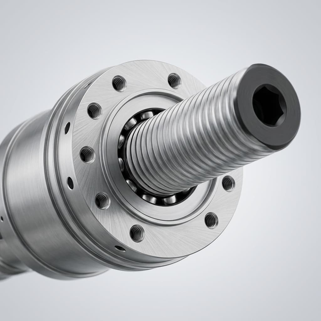
Custom vs. Standard Inverted Roller Screws: Lead Time, Cost Analysis, and RFQ Best Practices
A comprehensive procurement and engineering guide to choosing between standard and custom inverted roller screws, covering lead times, TCO, and RFQ checklists.
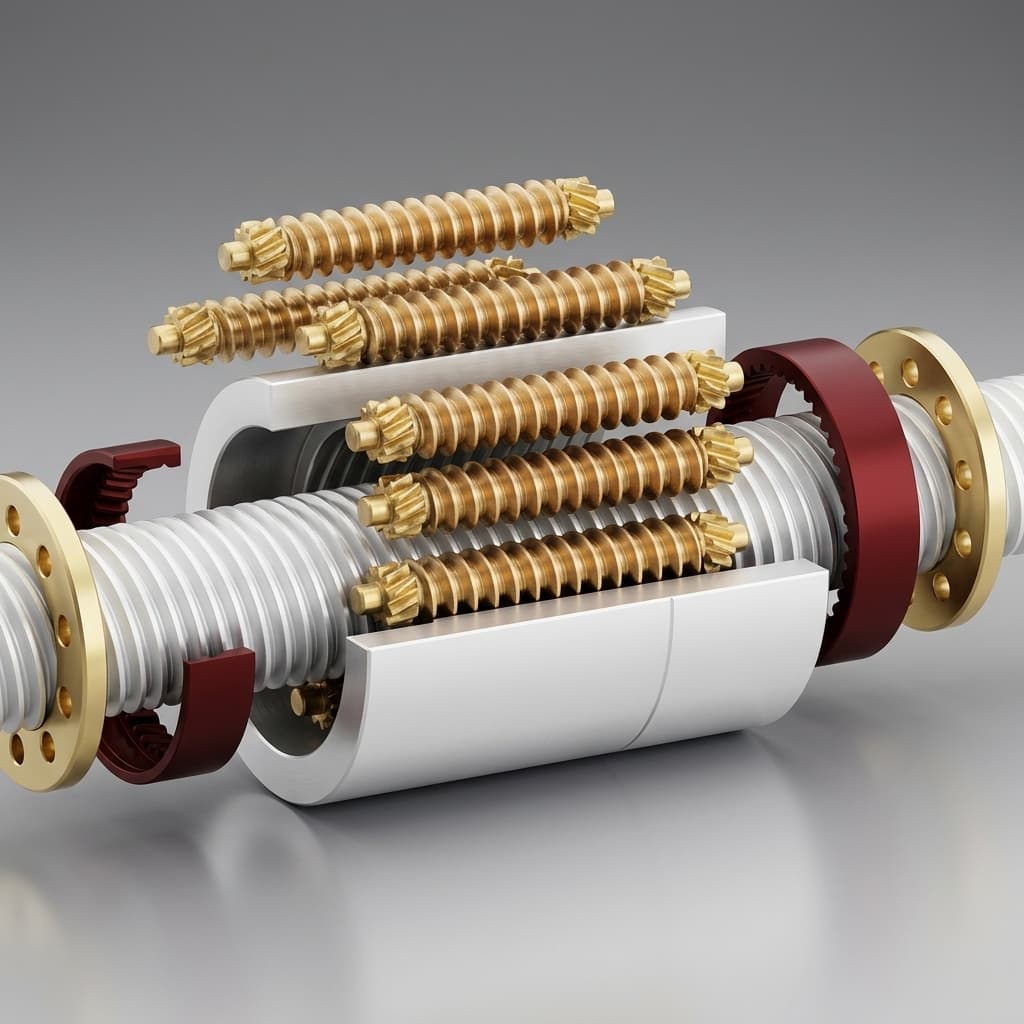
Inverted Roller Screw Shock Load and Impact Resistance: Static Safety Factors (s0), Brinelling Prevention, Snap-Through Dynamics, and Compliance Engineering
Assess inverted roller screw shock loads, static safety factors and brinelling risks. Use the worked example and RFQ checklist to request an engineering review.
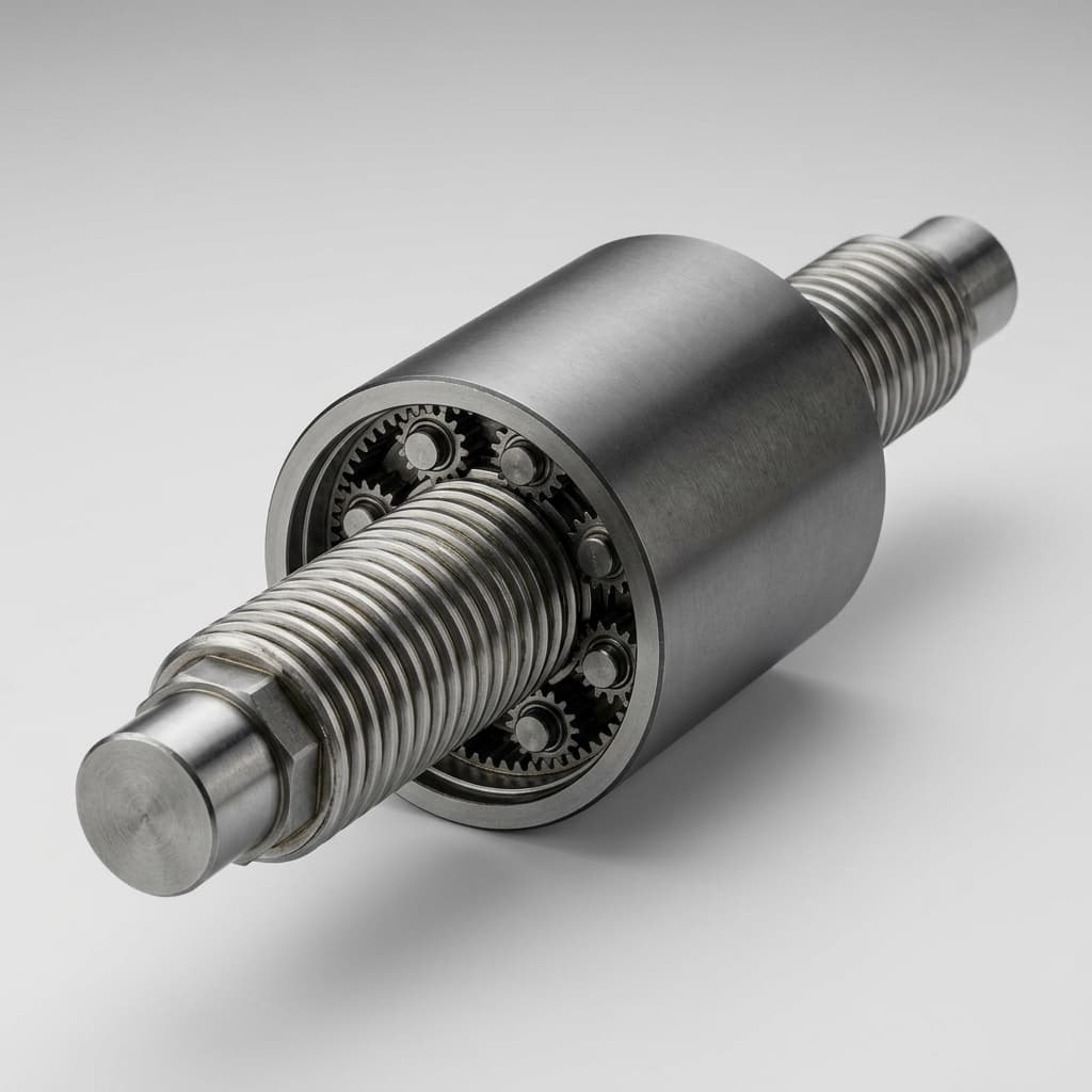
Inverted Roller Screw Lubrication Engineering: Synthetic Grease vs. Oil, EHL Film Breakdown, Relubrication Intervals, and Procurement Specifications
Compare inverted roller screw lubrication options, EHL limits, grease vs. oil, and relubrication planning. Use the RFQ checklist for an OEM supplier review.