
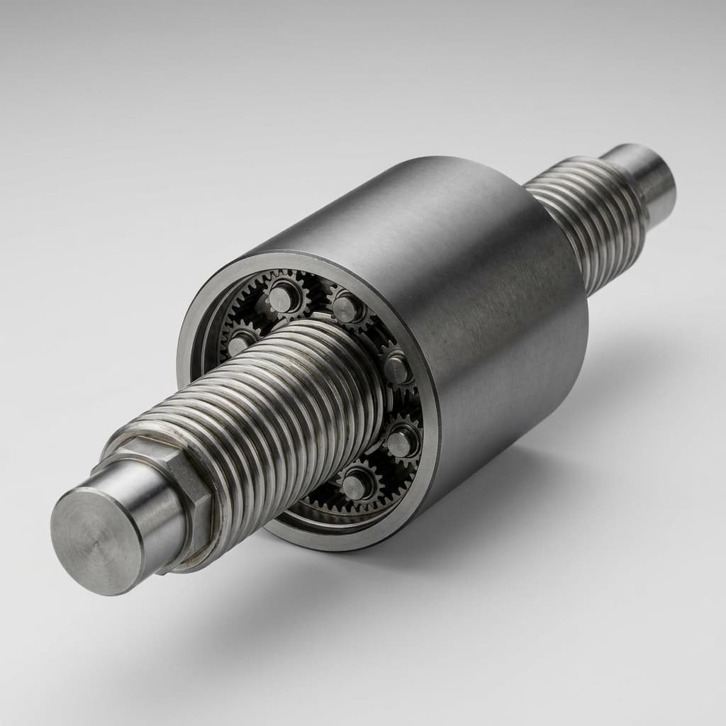
Inverted Roller Screw Lubrication Engineering: Synthetic Grease vs. Oil, EHL Film Breakdown, Relubrication Intervals, and Procurement Specifications
Compare inverted roller screw lubrication options, EHL limits, grease vs. oil, and relubrication planning. Use the RFQ checklist for an OEM supplier review.
Inverted roller screw lubrication should be specified alongside load capacity, speed, and thermal limits. Grease offers a compact supply system; circulating oil adds cooling and replenishment capability but needs a pump, filtration, return paths, and suitable seals. Neither choice guarantees a service interval without the screw manufacturer's approval for the actual operating cycle.
For an engineering drawing, functional specification, or supplier RFQ, resolve four questions:
- Film formation: Is base oil viscosity adequate at operating temperature and contact entrainment speed, including slow motion and reversals?
- Replenishment: Can lubricant reach both roller-to-nut and roller-to-screw contacts throughout the stroke and mounting orientation?
- Service access: Can maintenance add a measured charge and remove displaced lubricant without pressurizing seals or contaminating the motor?
- Evidence: Does the supplier's interval apply to the exact screw, lubricant product, fill, load-speed cycle, and environment?
Published and last reviewed: November 2, 2026. Scope: global OEM actuator engineering and procurement, using SI units. This is a selection and qualification framework, not a lubricant approval or a certified life calculation. The numerical examples below are reproducible arithmetic with assumed inputs; they are not measured actuator results. Manufacturer instructions and application tests govern final viscosity, fill, service intervals, and pressure limits.
Designing a high-thrust or high-duty linear drive? Review our inverted planetary roller screw mechanisms, explore integrated servo actuators, or submit your load-speed profile and thermal constraints for an engineering feasibility review.
1. Kinematic Differences and Centrifugal Starvation in Enclosed Nuts
Standard planetary roller screws can use a rotating screw or a rotating nut. Inverted designs commonly combine a long internally threaded nut with a compact roller assembly and translating output member. The name alone does not identify which parts rotate, how rollers are retained, or how lubricant enters the contacts. Request a section drawing showing these details before specifying ports.
In the rotating-nut arrangement considered here, lubricant can migrate toward the nut wall. That does not mean the inner contact necessarily runs dry: replenishment depends on roller motion, oil release, lubricant distribution features, stroke, and orientation. A feed route must be demonstrated rather than inferred from a grease fitting on the housing.
Centrifugal Acceleration Mechanics
For lubricant co-rotating at radius r and speed n, radial acceleration is:
a_c = ω² × r = (2π × n / 60)² × rIllustrative calculation: at r = 25 mm = 0.025 m and n = 3,000 rpm, ω ≈ 314.16 rad/s:
a_c ≈ 2,467 m/s² ≈ 251 gThis calculation describes acceleration, not grease shear degradation, oil separation rate, or a starvation threshold. Use it to justify checking distribution during representative speed, stroke, and orientation tests.
2. Elastohydrodynamic Lubrication (EHL) and Film Breakdown
EHL describes a fluid film formed where elastic contact deformation and pressure-dependent lubricant viscosity interact. At low entrainment speed, reversals, or inadequate supply, a contact may enter mixed or boundary lubrication even when the selected grease has a high nominal viscosity.
Film Thickness: What the Model Can Establish
Hamrock and Dowson's fully flooded point-contact study relates minimum film thickness to dimensionless speed, material, load, and ellipticity parameters. It is a useful starting point for understanding sensitivity, not a complete roller screw sizing rule. Geometry, inlet supply, temperature, and sliding must match the chosen model; a fully flooded elliptical-contact equation must not be treated as a universal line-contact or starved-grease model.
For procurement, request the contact geometry, lubricant viscosity at operating temperature, surface roughness, and assumptions behind the supplier's film estimate. Nut rpm and linear output speed are not interchangeable with local contact entrainment velocity. A low load exponent in one model does not make overload harmless: contact stress, deformation, fatigue, and heating still need separate checks.
Specific Film Thickness (Λ)
A common screening ratio compares minimum film thickness with composite RMS roughness:
Λ = h_min / sqrt(R_q,roller² + R_q,screw²)As an engineering screening convention, Λ > 3 suggests substantial separation, 1 ≤ Λ ≤ 3 suggests mixed lubrication, and Λ < 1 indicates increased boundary-contact risk. These are approximate categories, not acceptance limits or life guarantees. Full separation does not imply zero wear or infinite fatigue life, and boundary lubrication does not mean all fluid load support vanishes.
Assumed-input example: with both RMS roughness values at 0.25 µm, composite roughness is 0.354 µm. An assumed minimum film of 0.20 µm gives Λ ≈ 0.57; a film of 1.20 µm gives Λ ≈ 3.39. These calculations do not predict either film thickness: obtain that estimate from a suitable model or test.
Keep Bearing and Screw Life Methods Separate
The viscosity ratio κ = ν / ν₁ compares operating kinematic viscosity with a reference viscosity in bearing methods. It must not become an unsupported roller screw life multiplier. Likewise, ISO 3408-5 addresses ball screws, not inverted roller screw grease life. Require the screw supplier to identify its applicable rating method, lubrication assumptions, and qualification evidence.
3. Synthetic Grease: Base Oil, Thickeners, and Additives
The NLGI Grease Glossary distinguishes base fluid, thickener, consistency, additives, and lubrication regimes. In an RFQ, specify the actual lubricant product rather than treating an NLGI grade as a viscosity or performance rating.
- PAO-based grease: A candidate for broad-temperature service. Check the finished product's viscosity-temperature data and low-temperature torque; base oil family alone does not establish seal compatibility.
- Ester-based grease: A candidate when lubricity or temperature requirements justify it. Review water exposure, hydrolytic stability, and the exact seal compounds with both suppliers.
- Mineral-oil grease: A candidate where temperature, oxidation life, and maintenance access permit. Do not assume every mineral oil fails above a single temperature.
- PFPE-based grease: A specialized option for some vacuum, chemical, or contamination requirements. Confirm the entire assembly's suitability, including cleanliness, outgassing, conversion procedure, and approved thickener.
Lithium-complex, polyurea, and calcium-sulfonate-complex formulations should be compared as finished products. Thickener name alone does not establish continuous temperature capability, torque, water resistance, or compatibility with another grease. NLGI also cautions that dropping point is not an upper operating-temperature rating.
Solid Additives and PTFE Thickeners
Require explicit screw-manufacturer approval before introducing solid additives such as MoS₂ or graphite into precision rolling contacts. Do not claim a universal timing-gear jamming mechanism or failure time without product evidence. PTFE used as a thickener in an approved PFPE grease is different from adding coarse PTFE particles to another formulation; a blanket PTFE ban would contradict that distinction.
4. Engineering Comparison: Formulation and Acceptance Questions
This matrix is an RFQ comparison framework, not a table of approved viscosity grades or measured performance. Record the supplier's answer for each candidate lubricant.
| Selection item | Grease proposal | Circulating-oil proposal | Evidence to request |
|---|---|---|---|
| Base fluid | Identify full product and base oil family | Identify full oil product and additives | Technical data sheet and traceable product code |
| Viscosity | Base oil viscosity at 40°C, 100°C, and operating temperature | Oil viscosity at the same temperatures | Viscosity-temperature data and contact-film assumptions |
| Consistency | Manufacturer-approved NLGI grade and pumpability | Not applicable to liquid oil | Metering and cold-start delivery test |
| Heat removal | Housing conduction and any external cooling | Flow through the required heat-removal path | Duty-cycle thermal balance and measured temperatures |
| Replenishment | Distribution from a measured charge | Supply, return, and any scavenge requirement | Demonstrated delivery across stroke and orientation |
| Seals and materials | Finished grease and preservative compatibility | Leakage control and compatibility with the finished oil | Written compatibility statement and assembly test |
| Contamination | Wipers, purge capture, and clean filling | Filtration, breathers, and ingress control | Application-specific cleanliness acceptance criteria |
| Maintenance | Charge mass, access, interval, and purge instructions | Oil checks, filter service, alarms, and loss-of-flow response | Approved maintenance procedure for the supplied assembly |
| Qualification | Breakaway torque, running torque, wear, and temperature | Same checks plus flow and leakage | Representative duty test with recorded acceptance limits |
Comparing supplier proposals? Send the completed lubrication questions with your actuator RFQ so unresolved assumptions can be reviewed before quotation.
5. Recirculating Oil vs. Grease: When to Evaluate Active Lubrication
Evaluate oil when the approved grease system cannot demonstrate adequate replenishment, temperature control, or maintenance access for the required duty. Oil is not automatically better: pump failure, leaks, contamination, return routing, and motor isolation introduce additional requirements.
Speed Factor as a Screening Input
Speed factor = nut speed (rpm) × specified reference diameter (mm)Identify which diameter the manufacturer's catalogue uses. There is no universal speed-factor boundary at which every inverted roller screw must switch from grease to oil. Preload, geometry, lubricant, fill, and duty change the result; compare the exact assembly with its supplier's limits.
Duty Cycle and Heat Generation
For a resisting torque at a given speed:
P_loss = T_drag × ω = T_drag × (2π × n / 60)Assumed-input example: T_drag = 1.2 N·m at 2,400 rpm gives P_loss ≈ 301.6 W. That is the loss associated with the stated torque at that operating point, not the complete loaded actuator heat balance. Include load-dependent screw losses, bearings, seals, motor losses, and time at each duty point separately. Housing temperature cannot be calculated from this power alone without thermal resistance, cooling, and ambient conditions.
6. Planning Relubrication Intervals and Charge Mass
Grease service life and rolling-contact fatigue life describe different limits. Start with the manufacturer's interval for the exact screw and approved lubricant, then confirm whether its temperature, load, speed, stroke, orientation, and contamination assumptions cover the application. No universal hours-based formula is established by the sources cited here.
A Qualification Process for the Service Interval
- Document the supplier's initial interval and charge mass, including its source and operating assumptions.
- Run a representative cycle covering cold starts, hot operation, reversals, minimum travel, and the intended mounting orientation.
- Record temperatures, breakaway and running torque, leakage, purge condition, and wear inspections at agreed checkpoints.
- Confirm or shorten the interval using those records and supplier review. Extend it only with evidence covering the proposed duration and operating conditions.
- Define calendar limits, storage conditions, and abnormal-condition responses as well as operating-hour limits.
Scheduling example only: if a supplier has already approved 750 operating hours and the machine averages 120 operating hours/week, the planning interval is 750 / 120 = 6.25 weeks. This converts an approved interval into a schedule; it does not establish that 750 hours is safe for another actuator.
Initial Fill and Replenishment Are Separate Quantities
Initial mass (g) = net free volume (cm³)
                 × approved fill fraction
                 × product density (g/cm³)
Assumed-input example: a CAD-derived free volume of 20 cm³, a trial fill fraction of 0.30, and product density of 0.90 g/cm³ give 5.4 g. The 30% fraction is an example input, not a recommended fill. Deduct all internal components when calculating net volume; validate distribution and torque before approving the charge.
A replenishment shot cannot be inferred from nominal diameter and stroke alone. Agree its mass, delivery location, purge destination, metering tolerance, and whether the assembly must move during servicing. Overfilling can increase drag and pressure; a single free-volume percentage is not a universal failure threshold.
7. Internal Feed, Distribution, and Pressure Relief
Review possible feed routes against the assembly section drawing:
- Central axial feed: A hollow output member may permit delivery near the roller contacts. Drilling requires manufacturer review of buckling, fatigue, stress concentrations, cleanliness, and port location.
- Housing or nut feed: An external port may supply an annular distribution path. A rotating interface may require a rotary union or dedicated seal arrangement; a housing fitting alone does not prove delivery to the screw contacts.
- Purge and pressure control: Identify where displaced lubricant exits and how it is collected without entering the motor, encoder, or process area. Check the complete delivery path under cold-start and maximum pump pressure.
Relief valves are one possible solution, not a mandatory universal design. The manufacturer must set allowable cavity pressure, pressure drop, any relief setting, and the relation to seal limits. A grease gun's delivery pressure must not be treated as the actuator's allowable pressure; do not adopt a generic 0.5–1.0 bar setting without assembly-specific approval.
8. Drawing and RFQ Lubrication Checklist
Use this checklist before approving a production procurement package.
- 1. Duty and temperature: State load-speed-time profile, stroke, orientation, ambient range, and cold-start and stabilized temperature limits.
- 2. Product and viscosity: Record the approved lubricant product, base oil viscosity at 40°C and 100°C, and viscosity at the expected operating temperature.
- 3. Thickener and additives: Record consistency and thickener; identify restrictions and manufacturer-approved exceptions, including any solid additives.
- 4. Compatibility and cleaning: Confirm compatibility with seals, coatings, factory preservative, and previous lubricant. Require only the manufacturer's approved cleaning and changeover procedure.
- 5. Initial charge: Specify validated mass, tolerance, filling location, and distribution method; retain the basis for any free-volume calculation.
- 6. Feed routing: Approve port location, connection, delivery route, and any rotating seal or union requirements.
- 7. Purge and pressure: Specify the displaced-grease destination, cavity pressure limit, and any approved relief setting.
- 8. Run-in acceptance: Agree speed, travel, duration, temperature, and torque acceptance criteria for distribution and commissioning.
- 9. Service interval: Require interval, shot mass, calendar limits, and instructions tied to the actual duty profile.
- 10. Qualification and substitutions: Require test records, lubricant traceability, and written approval before changing the lubricant or operating envelope.
Engineering Drawing Callout Template
Complete these fields with supplier-approved values before releasing the drawing. Blank fields are unresolved requirements.
LUBRICATION SPECIFICATION — COMPLETE BEFORE RELEASE
1. APPROVED LUBRICANT: [manufacturer / product / data sheet revision].
   BASE OIL VISCOSITY: [__] mm²/s AT 40°C; [__] mm²/s AT 100°C.
   GREASE ONLY: NLGI [__]; THICKENER [__]; ADDITIVE RESTRICTIONS [__].
2. COMPATIBILITY / CLEANING: [approved preservative, seals, changeover procedure].
3. INITIAL CHARGE: [__] g ± [__] g VIA PORT [__].
4. DISTRIBUTION / RUN-IN: [speed, travel, duration, torque / temperature limits].
5. RELUBRICATION: [__] OPERATING HOURS / [__] CALENDAR LIMIT; [__] g PER SHOT.
6. PURGE DESTINATION [__]; CAVITY PRESSURE LIMIT [__]; RELIEF IF REQUIRED [__].
7. QUALIFIED DUTY / TEMPERATURE ENVELOPE AND TEST RECORD: [__].
   LUBRICANT SUBSTITUTION REQUIRES WRITTEN APPROVAL.
9. Frequently Asked Questions (FAQ)
Can MoS₂ grease be used in an inverted roller screw?
Use it only with explicit approval for the supplied screw. Solid-additive behavior depends on formulation and contact design. A general-purpose grease label does not establish suitability, and particle-induced timing-gear failure cannot be assumed for every design.
Can factory rust-inhibiting shipping oil remain when greasing?
Only when the manufacturer confirms compatibility with the approved lubricant. Otherwise use its cleaning and changeover procedure. Unapproved solvent cleaning of an assembled actuator may damage seals, remove required lubrication elsewhere, or leave residues.
Why does running torque rise after relubrication?
Fresh grease can increase churning resistance, but excess charge, a blocked purge path, contamination, and seal friction are also possible. Follow the approved distribution procedure and compare torque and temperature with commissioning records. Stop and investigate if limits are exceeded; do not assume an arbitrary percentage rise is normal.
How does vertical mounting affect grease distribution?
Gravity can alter oil distribution and leakage paths, especially during idle periods. Qualify the actual orientation, including upper contacts and reversals. Do not apply a universal percentage reduction to the interval or choose feed-hole positions without checking the mechanism's travel.
How can early lubrication breakdown be detected?
Trend temperature, breakaway torque, running torque, vibration, and leakage against a baseline measured at comparable load, speed, and ambient conditions. Changes can also indicate misalignment, seal damage, motor faults, or contamination; temperature or a frequency band alone cannot diagnose starvation. Set alarm and inspection limits during qualification.
Can a grease actuator be converted to circulating oil in the field?
Only after manufacturer review of seals, supply and return paths, filtration, flow monitoring, and motor isolation. A grease scraper may not retain oil. Filter ratings and oil cleanliness codes are different specifications; agree both for the application instead of assuming one universal filter establishes cleanliness.
10. Engineering Review and Procurement Support
A useful lubrication RFQ pairs the operating cycle with the assembly constraints: load, speed, stroke, orientation, temperature range, access for maintenance, target service interval, and proposed lubricant. Ask suppliers to return the completed checklist, unresolved assumptions, and qualification plan before comparing quotations.
Explore our inverted planetary roller screw mechanisms, check complete inverted roller screw servo actuators, or send your operating cycle and envelope drawing for an engineering review. The review should establish feasible options and required evidence before a lubricant or service interval is approved.
References and Technical Standards
These sources support the stated principles and terminology; they do not approve a specific inverted roller screw lubricant, charge, relief setting, or service interval.
- ISO 3408-5:2006 — Ball screws: Static and dynamic axial load ratings and operational life. Scope reference for ball screw rating methods. It is not an inverted roller screw relubrication standard.
- Hamrock and Dowson — Isothermal elastohydrodynamic lubrication of point contacts. III: Fully flooded results. NASA Technical Reports Server record, 1976. Source for fully flooded elliptical-contact film modeling and its assumptions; not a starved-grease service-life model.
- NLGI — Technical Grease Glossary. Definitions of base fluids, consistency, additives, EHL, and dropping point. These definitions do not substitute for finished-product data or assembly qualification.
Author

Categories
More Posts
Inverted Roller Screw Life Calculation: Dynamic Load Ratings (Ca), Cubic Mean Equivalent Load (Fm), L10h Fatigue Formulas, and Procurement Guarantees
Calculate inverted roller screw life with Ca, cubic mean load Fm and L10h formulas. Check the worked duty cycle and RFQ checklist, then request a sizing review.
Replacing Hydraulic Cylinders with Inverted Roller Screws: A Total Cost of Ownership (TCO) Analysis
Use this TCO guide to compare hydraulic cylinders with inverted roller screws across energy, maintenance, ESG risk, precision, and migration limits.
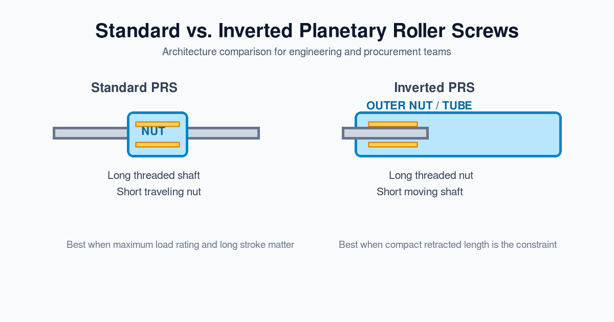
Inverted vs. Standard Planetary Roller Screws: Engineering & Procurement Guide
A comprehensive decision framework comparing standard and inverted planetary roller screws. Learn the engineering trade-offs in load capacity, packaging, cost, and lubrication.