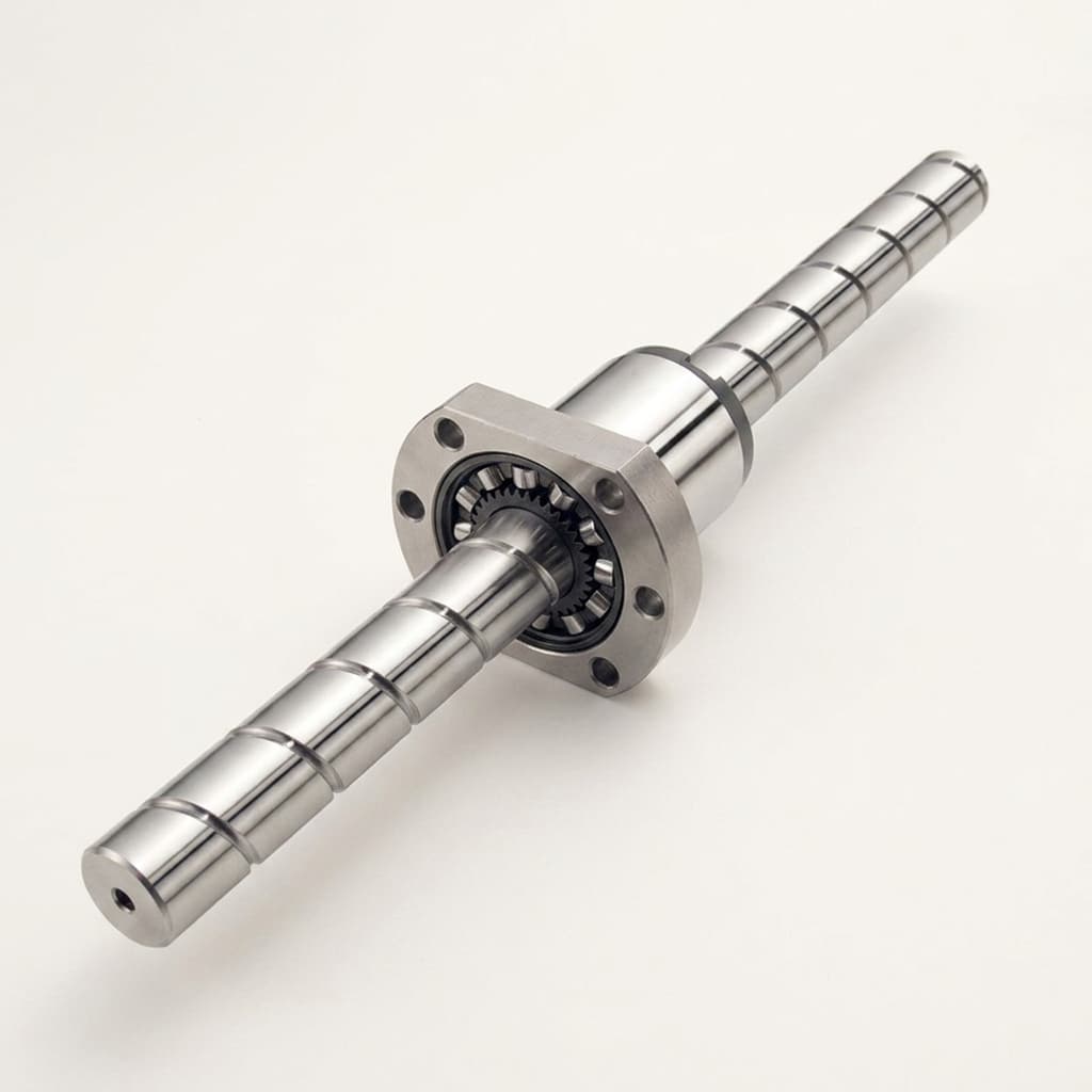
Inverted Roller Screw Life Calculation: Dynamic Load Ratings (Ca), Cubic Mean Equivalent Load (Fm), L10h Fatigue Formulas, and Procurement Guarantees
Calculate inverted roller screw life with Ca, cubic mean load Fm and L10h formulas. Check the worked duty cycle and RFQ checklist, then request a sizing review.
Inverted roller screw life calculation starts with the supplier’s basic dynamic axial load rating (Ca), a revolution-weighted equivalent load (Fm), and a matched fatigue-life exponent. For a catalog using the cubic model, L10 = (Ca / Fm)^3 × 1,000,000 revolutions. Convert this to L10h using the speed averaged over the hours you actually intend to quote. Motor RMS torque, machine cycle hours, and a fatigue warranty answer different questions.
Procurement teams and mechanical systems engineers frequently encounter costly project hurdles when sizing high-force electromechanical actuators:
- Sizing screws from drive software RMS torque instead of the appropriate fatigue equivalent load.
- Comparing a supplier’s cycle-hour claim with a requirement stated in active motion hours.
- Ignoring stationary high-force holds, short oscillations, preload, contamination, or mounting misalignment.
- Accepting catalog Ca without identifying its rating method, product configuration, and service conditions.
Published and reviewed: November 8, 2026. Scope: global OEM engineering and procurement, using SI units. This guide provides a reproducible, hypothetical five-phase servo-press calculation and a ten-point RFQ checklist. It is a screening method, not a physical endurance test, a certified actuator selection, or a guarantee for an individual screw. The example uses the cubic model and reliability factors in the Ewellix roller screw catalog, pages 21–22 and 44. Confirm the method for the actual inverted design before ordering.
Sizing an actuator or preparing an OEM specification? Review our inverted planetary roller screw architecture, explore integrated servo electric cylinders, or send your application duty cycle for a factory sizing review.
1. Rolling Contact Fatigue Mechanics in Inverted Roller Screws
An inverted planetary roller screw converts rotary torque into linear thrust through multiple threaded planetary rollers and an internally threaded nut. The rotating and translating members depend on the selected architecture. Multiple thread contacts share the axial load; their exact shape and load distribution depend on geometry, contact angle, manufacturing accuracy, and preload.
Rolling fatigue and service life
Under repeated rolling contact, cyclic stresses can initiate cracks below or near the raceway surface. Crack growth can eventually produce flaking or spalling. This is one failure mechanism. Abrasive wear, corrosion, lubrication failure, seal damage, and lost positioning accuracy can end service life sooner, even when a nominal fatigue calculation looks adequate.
L10 is a statistical rating: under the stated model and conditions, 90% of a sufficiently large population of identical assemblies is expected to reach or exceed that fatigue life. It does not establish an observed failure date or a maintenance-free interval for one actuator.
Basic dynamic axial load rating (Ca)
Ca represents the constant axial, centrally applied load associated with a nominal rating life of one million revolutions under the supplier’s rating method. Keep the units consistent: Ca and Fm may both be in N or both in kN. Their ratio is dimensionless.
Catalog Ca depends on screw and nut geometry, roller count, engaged threads, material, heat treatment, and contact distribution. Do not infer it from outside diameter alone. Ask whether the quoted rating applies to the exact nut length, preload, lead, and load direction supplied.
ISO 3408-5:2006 directly addresses ball screws. A roller screw maker may use related rating principles, as Ewellix does, but that does not make every inverted roller screw automatically certified to this standard. Likewise, bearing-standard equations are not a substitute for the roller screw supplier’s approved calculation.
Basic static axial load rating (C0a) and static safety factor (S0)
C0a concerns permissible contact deformation under static loading, rather than fatigue endurance. It is not a recommended continuous working load or a hard failure threshold. Calculate:
S0 = C0a / F0,max
F0,max must include the greatest credible axial load, including a loaded hold, emergency stop, acceleration transient, or collision case where applicable. Select the required S0 with the supplier and machine risk assessment. The example below assumes 2.5 for screening; this is not a universal press, aerospace, or medical requirement. Check the rod, end fittings, bearings, retaining features, and housing separately.
2. Mathematical Formulation: Cubic Mean Equivalent Dynamic Load (Fm)
Real actuators rarely run at constant force and speed. A servo press advances rapidly under low load, slows to press at high force, holds position, retracts, and waits for the next workpiece. The equivalent load is a hypothetical constant axial load producing the same calculated rolling fatigue exposure as the changing cycle.
Discrete time and revolution weighting
Split the motion into phases with force magnitude Fi, relative rotational speed magnitude ni in rpm, and duration ti in seconds. Use magnitudes so that reversing motion cannot cancel fatigue exposure. Then calculate:
Ni = abs(ni) × ti / 60                         [revolutions in phase i]
Ncycle = sum(Ni)                              [revolutions per cycle]
Fm = (sum(abs(Fi)^p × Ni) / sum(Ni))^(1/p)      [same force unit as Fi]
For the cubic model, p = 3. A stationary hold has Ni = 0 and adds no rolling revolutions to this model, even when its force is high. It still requires static and holding-system checks. If the servo dithers during a nominal hold, include that measured micro-motion and seek supplier guidance on oscillatory wear.
The Ewellix catalog uses a cubic roller screw life model. Do not substitute the p = 10/3 exponent used for roller bearings simply because the product contains rollers. Ca, p, the reliability factor, and the life equation must come from one compatible method. Choosing p = 3 is not automatically conservative relative to a different rating system.
Distance-based equivalent load
For constant lead Ph in mm/rev, Ni = abs(si) / Ph, where si is travel in a phase. Therefore:
Fm = (sum(abs(Fi)^p × abs(si)) / sum(abs(si)))^(1/p)
Sum absolute travel in both directions. The net displacement of a complete out-and-back cycle is zero, but its fatigue exposure is not. For nonuniform acceleration or force, use smaller segments or integrate the measured force over travel; preserve the peak-load check separately.
Continuous linear force ramp
For constant speed and a force rising linearly over travel between nonnegative Fmin and Fmax, the exact cubic equivalent is:
Fm = ((Fmax^4 - Fmin^4) / (4 × (Fmax - Fmin)))^(1/3)
For equal endpoint forces, use that constant force. This expression applies to one ramp segment; combine it with the other phases using their travel or revolutions. A force ramp linear in time at changing speed needs revolution weighting rather than this shortcut.
Why a motor RMS value can overstate screw life
Motor thermal sizing often uses RMS torque because electrical heating depends on current squared. The cubic screw model uses a different exponent and weights exposure by revolutions. For a hypothetical two-phase cycle at equal speed, take 10 kN for 90% of motion time and 100 kN for 10%:
- Arithmetic mean:
10 × 0.9 + 100 × 0.1 = 19.0 kN. - RMS load:
(10^2 × 0.9 + 100^2 × 0.1)^0.5 = 33.02 kN. - Cubic mean:
(10^3 × 0.9 + 100^3 × 0.1)^(1/3) = 46.55 kN.
Using RMS in this cubic life equation would overstate calculated life by approximately (46.55 / 33.02)^3 = 2.80. This is a mathematical comparison, not an observed field-failure claim. At unequal speeds the weighting changes; a high-force stationary dwell is not equivalent to a moving press stroke.
3. Motion Life vs. Machine Cycle Hours
Both motion hours and full-cycle hours can be valid reporting units. The error is comparing them without identifying the denominator and the repeating duty cycle.
Nominal life in total revolutions (L10)
Once Fm is known, calculate basic rating life:
L10 = (Ca / Fm)^p × 1,000,000 revolutions
Some catalogs express L10 in millions of revolutions and omit the multiplier. This article uses total revolutions throughout. Record the convention on every calculation sheet to avoid an error of one million.
Conversion to operating hours (L10h)
For the same repeated cycle:
tactive = sum(ti for phases with ni > 0)
Tcycle = sum(all ti)
nactive = 60 × Ncycle / tactive               [rpm]
ncycle = 60 × Ncycle / Tcycle                 [rpm]
L10h,motion = L10 / (60 × nactive)             [hours of rotation]
L10h,cycle = L10 / (60 × ncycle)               [hours of repeated cycles]
If motion occupies half the cycle, cycle-hour life is twice motion-hour life for the same total revolutions. This does not create extra mechanical endurance. Cycle hours describe elapsed time while that exact production cycle repeats; they do not automatically include overnight shutdowns, maintenance, or different shift patterns.
In procurement agreements, require life in total revolutions, cumulative absolute travel, or completed production cycles first, followed by the hourly convention. Also specify the force and motion profile: the same travel at higher force will not have the same predicted life.
4. Engineering Derating Factors and Reliability
Catalog ratings assume defined operating conditions. Avoid generic hardness, temperature, shock, and short-stroke tables unless the selected manufacturer supports those factors for the exact product. Different catalogs place corrections on load, capacity, or life; mixing their conventions can reverse a penalty or count it twice.
For a transparent illustrative capacity-factor convention, define fh, ft, and fst as capacity reductions between zero and one, fw as a load multiplier of at least one, and a1 as a life multiplier:
Cam = Ca × fh × ft × fst / fw
Lreliability = a1 × (Cam / Fm)^p × 1,000,000 revolutions
Cam is the effective capacity in this convention. A smaller fst must reduce capacity and life; dividing by a factor below one would incorrectly increase them. These symbols do not establish approved factor values. Do not add an ISO 281 bearing-system factor to this roller screw model without supplier validation.
| Parameter | Meaning | Required input or evidence | Selection boundary |
|---|---|---|---|
| Ca and p | Dynamic capacity and matched life model | Model-specific catalog or signed calculation | Keep capacity, exponent, and life units compatible |
| fw | Applied-load allowance | Agreed treatment of impact and uncertainty | Avoid double counting shocks already in Fi |
| fh | Material/hardness capacity correction | Material and heat-treatment specification | No universal HRC-to-life conversion is assumed |
| ft | Temperature capacity correction | Raceway temperature and material/lubricant limits | A nominal capacity factor does not approve grease or seals |
| fst | Short-stroke capacity correction, if applicable | Supplier-approved stroke and lubrication assessment | No universal stroke-to-lead threshold or factor is assumed |
| a1 | Reliability life multiplier | Reliability table from the chosen method | Ewellix 2020 catalog: 0.62 at 95%, 0.21 at 99% |
| S0 | Static safety factor | Peak load and C0a for the supplied assembly | Check holds and transients independently of fatigue |
| Preload | Internal contact loading | Preload class and internal-load model | External force alone may understate contact demand |
| Lubrication | Film, cleanliness, and replenishment | Lubricant specification and maintenance interval | Wear can limit service life before rolling fatigue |
The numerical reliability factors above belong to the cited catalog, page 21. They are not universal actuator warranty terms. For a 95% target under that method, L5 = 0.62 × L10; therefore the required basic L10 must be longer than the requested L5.
Short-stroke motion needs separate approval
Small oscillations repeatedly load limited raceway regions and may fail to redistribute lubricant. The Ewellix catalog, page 22, flags strokes shorter than the nut length and short oscillations for additional consideration. It does not justify a universal two-to-four-lead threshold or a fixed 100 mm purge stroke for every inverted assembly.
Provide the minimum stroke, nut and roller geometry, oscillation frequency, dwell force, orientation, and lubricant to the supplier. Agree any redistribution stroke and its safe travel limits with the machine designer. A nominal fatigue calculation alone cannot approve fretting or false-brinelling resistance.
5. Worked OEM Sizing Example: 140 kN Electric Servo Press
This hypothetical example illustrates the calculation; it is not a tested machine or a selected commercial part. Assume an inverted roller screw with a rotating nut, a nonrotating translating output, and 10 mm/rev lead. The one-way tool stroke is 330 mm, with a stationary hold after pressing.
Assumed sizing requirements
- Target pressing and holding force: 140 kN, approximately 14.3 metric tonnes-force.
- Rapid advance/retract speeds: 250/300 mm/s.
- Required fatigue life: 20,000 motion hours at 95% reliability, denoted L5h,motion.
- Cubic model p = 3 and a1 = 0.62, following the cited Ewellix catalog for this illustration.
- Illustrative load allowance fw = 1.3; fh = ft = fst = 1.0 provisionally. These assumptions require supplier confirmation, particularly for the 30 mm pressing segment.
- The phase forces are assumed to include external axial inertia and process loads. Preload, mounting, thermal, and oscillation effects remain separate approval items.
Five-phase duty cycle
The full cycle is exactly 10 seconds. Speeds and travel below are magnitudes; retraction reverses direction. The coining phase holds position without modeled rotation.
| Phase | Description | Force [kN] | Speed [mm/s] | Relative speed [rpm] | Time [s] | Absolute travel [mm] | Revolutions |
|---|---|---|---|---|---|---|---|
| 1 | Rapid approach | 4 | 250 | 1,500 | 1.20 | 300 | 30 |
| 2 | Controlled pressing | 140 | 15 | 90 | 2.00 | 30 | 3 |
| 3 | Stationary coining hold | 140 | 0 | 0 | 1.50 | 0 | 0 |
| 4 | Retraction | 6 | 300 | 1,800 | 1.10 | 330 | 33 |
| 5 | Stationary part loading | 0 | 0 | 0 | 4.20 | 0 | 0 |
| Total | Complete cycle | — | — | — | 10.00 | 660 | 66 |
Step 1: Calculate active and cycle speeds
Only phases 1, 2, and 4 involve rotation. The stationary high-force hold is excluded from motion time, along with stationary part loading:
tactive = 1.20 + 2.00 + 1.10 = 4.30 s
sum(ni × ti) = 1500 × 1.20 + 90 × 2.00 + 1800 × 1.10 = 3960
Ncycle = 3960 / 60 = 66 revolutions
nactive = 3960 / 4.30 = 920.93 rpm
ncycle = 3960 / 10.00 = 396.00 rpm
Step 2: Calculate cubic mean load
Weight each moving phase by its revolutions, keeping force in kN:
sum(Fi^3 × Ni) = 4^3 × 30 + 140^3 × 3 + 6^3 × 33
              = 1,920 + 8,232,000 + 7,128
              = 8,241,048 kN^3·rev
Fm = (8,241,048 / 66)^(1/3) = 49.982 kN
The pressing phase contributes approximately 99.89% of this modeled fatigue exposure while occupying 20% of total cycle time. This result is specific to the assumed load and travel. The stationary hold contributes no revolutions, but its 140 kN load remains relevant to static capacity and holding performance.
Step 3: Convert the required reliability life to revolutions
Do not label a 95% requirement L10. Under the selected reliability convention, it is L5:
Required L5 = 20,000 × 60 × 920.9302326
            = 1,105,116,279 revolutions
Required basic L10 = L5 / 0.62
                   = 1,782,445,611 revolutions
Equivalent basic L10h,motion = 20,000 / 0.62 = 32,258.06 h
At the requested 95% reliability target, 1,105,116,279 / 66 corresponds to approximately 16.74 million production cycles, or 46,511.63 cycle hours at 10 seconds per cycle. The basic L10 number would represent 27.01 million cycles at 90% reliability. These are different statistical targets; neither is a guaranteed production count.
Step 4: Determine required dynamic capacity
Required Cam = 49.9819086 × (1,782,445,611 / 1,000,000)^(1/3)
             = 606.02 kN
Required Ca = Cam × fw / (fh × ft × fst)
            = 606.02 × 1.3 = 787.82 kN
Use Ca of at least 788 kN as a screening requirement under these provisional assumptions. Calculate with unrounded intermediate values, then select an approved catalog or custom rating. If short-stroke, preload, thermal, or lubrication conditions require further reductions, the required nominal capacity increases.
Step 5: Check static capacity and release conditions
With the assumed 140 kN peak and illustrative S0 = 2.5, C0a ≥ 2.5 × 140 = 350 kN. If the actual emergency-stop or collision load is larger, repeat this check with that load. A dynamic rating does not imply a particular static rating, and neither establishes a shaft diameter.
The outcome is a requirement sheet: 10 mm lead, the stated duty cycle, Ca at least 788 kN under the stated method, and C0a at least 350 kN under the stated peak assumption. It is not approval of a 48–60 mm screw or any particular actuator. Supplier review must also cover geometry, preload, buckling, speed limits, support bearings, end fittings, lubrication, and the complete load path.
Send this load-cycle table with your RFQ and ask the supplier to return its assumptions, matched rating method, and unresolved limits alongside the proposed part number.
6. Sizing Pitfalls and Mechanical Boundaries
Unintended radial loads and moments
The equations assume centered axial loading. Side loads, bending moments, and misalignment can concentrate contact loads and invalidate the simple life estimate. Use the inverted roller screw side-load and mounting guide when reviewing external guides and connection alignment.
Do not treat a small fixed percentage of Ca as universally permissible radial load. Provide the actual lateral force and moment envelope to the supplier. External linear guides and appropriate articulated connections must support the machine load without creating a second, misaligned constraint on the actuator.
Temperature and direct-drive motor integration
A frameless motor surrounding the rotating nut can conduct heat into the screw, bearings, and lubricant. Ambient temperature alone does not establish raceway temperature. Evaluate the sustained cycle, cooling path, lubricant viscosity at operating temperature, seals, and material limits.
Use temperature sensors and supplier-approved cooling where required. A specific temperature does not universally soften all raceway steels by a fixed amount; heat-treatment history and exposure duration matter. Excess heat can restrict grease or bearing operation before a nominal material capacity limit is reached.
Preload and measured cycle accuracy
Preload increases internal contact loading even when external thrust is small. Its influence depends on the nut configuration and the load sharing between contact groups. Ask for the preload-aware calculation rather than adding a fixed percentage to every phase. Capture acceleration, reversals, and any servo hunting at the resolution needed to represent peak loads and cumulative travel.
7. Procurement and Engineering RFQ Checklist
Before freezing a design or issuing an order, complete these ten checks:
- 1. Full duty cycle: Record force, direction, travel, velocity, duration, acceleration, and loaded stationary holds.
- 2. Matched rating method: Identify Ca, C0a, p, life units, preload configuration, catalog revision, and load-direction limits.
- 3. Equivalent load: Verify revolution or absolute-distance weighting; do not substitute motor RMS torque.
- 4. Hour convention: Specify motion hours, repeated-cycle hours, revolutions, and completed cycles consistently.
- 5. Short strokes: Obtain an explicit assessment of minimum stroke, oscillations, and lubricant redistribution.
- 6. Environment: Agree lubrication, cleanliness, sealing, cooling, temperature limits, and maintenance intervals.
- 7. Corrections: Document factor definitions and values; confirm no penalty increases capacity or duplicates a measured load.
- 8. Static and structural limits: Check peak loads, chosen S0, buckling, bearings, fittings, guides, and holding arrangements.
- 9. Reliability: State survival probability and its compatible life factor; distinguish calculated fatigue life from service life.
- 10. Acceptance and warranty: Agree measurable failure criteria, test conditions, inspection method, exclusions, records, and remedy in writing.
Turn a rating calculation into a procurement agreement
A useful RFQ asks the supplier to confirm the selected part and drawing revision against the attached duty-cycle revision, target reliability, and service conditions. Define fatigue failure separately from unacceptable backlash, positioning drift, noise, or leakage. Specify inspection intervals and how raceway damage will be documented and attributed.
If the parties choose a numerical spalling-area threshold, identify the inspected surface, measurement method, and who approves the assessment. Do not attribute a universal 0.5 mm² warranty threshold to a damage-classification standard. Define sample size and statistical acceptance with the supplier when an endurance demonstration is required; a single successful test does not prove 95% population reliability.
The purchase agreement should state the actual remedy and exclusions. A statistical L10 or L5 calculation alone creates no individual-unit replacement guarantee. Keep lubricant service logs, load-cycle records, temperature records, serial numbers, and agreed return-inspection procedures so a claim can be assessed against the same assumptions used for sizing.
8. Frequently Asked Questions
Does L10 guarantee that no screw will fail earlier?
No. L10 describes a modeled 90% survival level for a population under specified conditions. It is not a guaranteed minimum for every unit. Earlier failures can also arise from mechanisms outside rolling fatigue. For higher required reliability, use the supplier’s compatible correction method and define warranty obligations separately.
Can I use the RMS torque from servo sizing software?
Use it for its intended motor-sizing purpose. For screw fatigue, derive axial loads for each phase, account for the actual speed or travel, and use the selected screw rating model. The equal-speed example above shows why RMS and cubic means differ; unequal speeds require their own revolution weights.
Does preloading the nut reduce life?
Preload can increase internal contact demand and friction. Its effect is configuration-dependent; no universal external-load multiple makes it disappear for all inverted screws. Request the supplier’s internal-load calculation for the proposed preload class, especially for lightly loaded positioning cycles.
Is L50 the mean life, or five times L10?
L50 is a median fatigue life, corresponding to 50% survival. It is not an arithmetic mean. The L50-to-L10 ratio depends on the statistical distribution and its parameters; this guide assumes no fixed multiplier. Do not convert an L10 rating into an average service-life or warranty claim.
Does every stroke under 50 mm need the same derating?
No. Relevant geometry, loaded length, oscillation frequency, lubricant, and kinematics vary. Ask the supplier to assess the actual motion. Do not program an arbitrary purge stroke without checking machine travel, tooling clearance, and the approved lubrication procedure.
Are tensile and compressive ratings identical?
Confirm both directions on the approved assembly drawing. Even if the screw contacts support bidirectional loading, the push rod, attachments, bearings, and retaining features can impose different limits. Compression additionally requires a buckling check where relevant.
Can appearance alone distinguish fatigue from wear?
Flaking, scoring, corrosion, and debris offer clues, but overlapping damage can obscure the initiating cause. Record lubricant condition, operating history, photographs, and raceway inspection results. Use an agreed failure-analysis method rather than assigning warranty liability from a single photograph.
How does speed affect life?
At unchanged equivalent load and within approved limits, the basic equation gives the same number of revolutions. Higher average speed consumes them in fewer operating hours. Actual speed also affects heat, lubrication, acceleration demand, and mechanical limits, so practical service life may change as well.
9. Sourcing Specifications and Next Steps
A useful sizing request gives the supplier enough information to assess capacity, packaging, and service conditions together. Include the full duty-cycle table; the desired reliability and life units; allowable envelope, lead, stroke, and interfaces; the preload and positioning requirements; and the expected environment and maintenance plan.
Ask for a calculation sheet and approved drawing with any unresolved assumptions clearly identified. Do not approve a substitution from dynamic capacity alone: a larger assembly may change inertia, motor demand, cooling, mounting, and available travel.
For an active actuator project, explore our inverted planetary roller screws, review integrated roller screw actuators, or discuss custom roller screw manufacturing. Submit your duty-cycle spreadsheet for a factory sizing review and request confirmation of the rating method, application limits, and quotation-specific warranty terms.
10. References and Source Boundaries
Sources checked November 8, 2026. The arithmetic is reproducible from the stated inputs; it is not measured endurance data or a customer case study.
- ISO 3408-5:2006 — Ball screws, Part 5: Official ISO catalog record. Establishes the scope of the ball-screw load-rating and operational-life standard. The public record does not certify the inverted design in this example or expose every calculation clause.
- Ewellix, Roller screws, PUB IL-05003/1-EN, June 2020: Manufacturer catalog hosted by distributor ConCar (PDF, approximately 11.7 MB). Pages 21–22 explain rating and service-life boundaries; page 44 gives the cubic calculation model. Page 21 supplies the 0.62 factor used here for 95% reliability. Confirm any later product-specific revision with the supplier.
- Schaeffler industrial media library: Current technical-document discovery portal, reached by the former Ewellix asset link during this review. Use it to locate current product documents. It is a document-discovery resource, not independent evidence for the worked calculation or a substitute for the identified catalog revision.
Author

Categories
More Posts
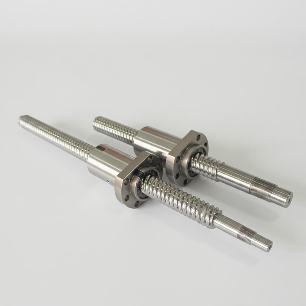
Integrating Inverted Roller Screws with Frameless Hollow-Shaft Motors: Direct-Drive Actuator Engineering, Thermal Management, and Procurement Guide
Integrate inverted roller screws with frameless hollow-shaft motors. Compare thermal paths, bearing interfaces and sourcing options, then prepare your OEM RFQ.
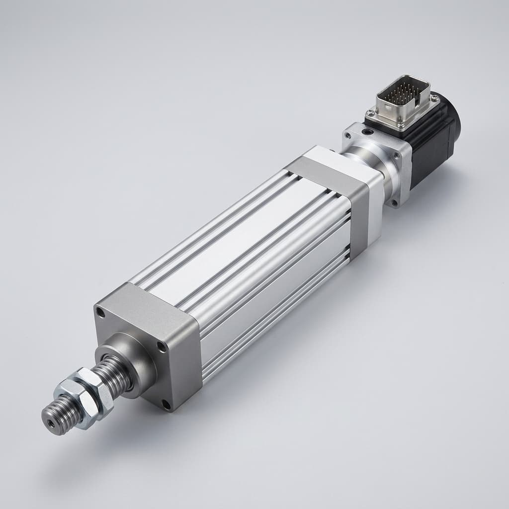
Radial Load Isolation and Moment Decoupling in Inverted Roller Screw Actuators: Permissible Side-Load Limits, External Guidance Sizing, and Articulated Mounting Architecture
Size inverted roller screw side-load isolation with guide reaction examples, mounting checks and supplier-specific limits. Prepare your actuator RFQ checklist.
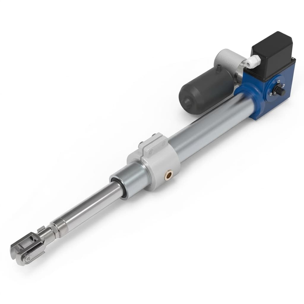
The Manufacturing Process of Inverted Roller Screws: Why Internal Thread Grinding Matters
Go behind the scenes at our factory to understand the complexities of internal thread grinding and why it dictates the quality of inverted roller screws.