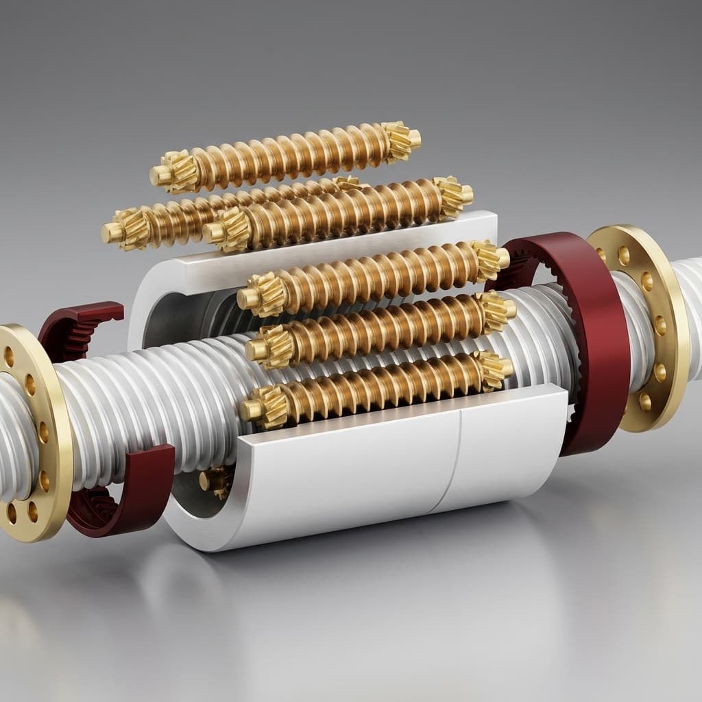
Inverted Roller Screw Shock Load and Impact Resistance: Static Safety Factors (s0), Brinelling Prevention, Snap-Through Dynamics, and Compliance Engineering
Assess inverted roller screw shock loads, static safety factors and brinelling risks. Use the worked example and RFQ checklist to request an engineering review.
Inverted roller screw shock load and impact resistance must be evaluated against the peak axial force, not only the nominal thrust or fatigue-life rating. Begin with the incoming kinetic energy, the effective stiffness of the complete load path, and the supplier's basic static axial load rating, C0a. The screening ratio is s0 = C0a / Fmax. A larger ratio alone does not establish survival of a machine crash: bearings, attachments, guides, roller synchronization components, and the extended pushrod need separate checks.
Engineers and procurement teams replacing hydraulic cylinders or specifying servo presses commonly need to resolve four questions:
- Does the quoted static capacity cover the actual transient force, rather than the average production load?
- What happens when a punch breaks through and the press frame releases stored elastic energy?
- Can added compliance reduce the contact force without unacceptable lost motion or rebound?
- Which calculations, inspection records, and acceptance tests must accompany the RFQ?
Published and reviewed: November 11, 2026. Scope: Global OEM machine builders, mechatronics designers, and technical procurement teams; SI units. This article provides a preliminary engineering method and an illustrative calculation, not hardware test data or certification of a particular actuator. All example dimensions, ratings, and safety-factor targets are assumed inputs. Final selection requires the manufacturer's model-specific limits and a validated machine load history.
For a design review, compare our inverted planetary roller screw architecture and integrated roller screw actuators, then send the moving mass, contact speed, stroke, and force-time profile.
1. Contact Mechanics and the Physics of Brinelling Under Shock
A roller screw transfers axial force through multiple roller-thread contacts. Their geometry and load sharing can provide high load capacity within a compact envelope, but the contacts still deform under load. Misalignment, preload, surface hardness, and engagement length change the local stress. Do not infer a universal allowable Hertzian pressure or impact capacity from the product family name.
True brinelling describes permanent contact indentation caused by excessive load. It differs from false brinelling: wear associated with small oscillations or vibration at loaded contacts. Similar-looking marks can have different causes, so inspection history matters. ISO 15243:2017 provides rolling-bearing damage terminology and visual classification; it does not certify roller screw shock capacity.
"Static" in a static load rating concerns the permanent-deformation criterion. A brief impact can therefore require a static-capacity check even while the machine is moving. Repeated impacts also require fatigue and wear assessment. Passing one check does not replace the other.
Mathematical Derivation of Peak Impact Force
For a single moving mass striking an initially unloaded, linear elastic load path, with no damping and no additional drive work during compression:
Kinetic energy:             Ek = 0.5 × m × v²
Maximum spring energy:      Es = Fpeak² / (2 × k)
Energy balance:             Ek = Es
Peak force:                 Fpeak = v × sqrt(k × m)
Maximum elastic deflection: xpeak = Fpeak / k
Use kilograms for m, metres per second for v, and newtons per metre for k. Stiffness supplied in N/µm must be multiplied by one million. Mixing these units understates peak force by a factor of one thousand.
The effective stiffness includes the screw, support bearings, housing, frame, tool, and mounting interfaces. For linear elements in series, 1/keq = 1/k1 + 1/k2 + .... A stiff screw does not make the entire machine equally stiff. Hydraulic stiffness also depends on trapped fluid volume, cylinder area, entrained air, hoses, and valve response; hydraulic relief is not an automatic impact-survival guarantee.
The square-root relationship gives a useful comparison: reducing effective stiffness to one quarter reduces the calculated force to one half at unchanged mass and speed. It also increases travel. A spring stores energy and can return it as rebound; a damper dissipates energy. Check both peak force and the available stopping distance.
This lumped model cannot resolve local stress waves, backlash closure, nonlinear contact stiffness, or an active motor continuing to deliver energy. Where appropriate, include rotational inertia through the transmission. For a directly coupled screw of lead p in metres per revolution, equivalent linear inertia is mrot = J × (2π/p)², with J in kg·m². Reflect gearing correctly and avoid counting an inertia twice. For short pulses or multiple structural modes, use a validated transient model or measurement.
2. Failure Modes Specific to Inverted Roller Screws Under Shock
The inverted arrangement changes packaging and the force path; the exact roller retention, synchronization, and rotating member depend on the design. Ask for a section drawing before assuming that all inverted screws share the same failure mechanism.
1. Planetary Timing Gear and Retention Damage
Where timing gears or retaining features control roller motion, rapid deceleration and slip can load those components independently of the axial thread rating. C0a is not a gear-tooth shear rating. Request a design-specific assessment of the deceleration event, roller inertia, and retention arrangement, rather than applying a universal acceleration limit.
2. Contact Edge Loading and Roller Skewing
Radial loads, bending moments, and angular misalignment can concentrate the axial load onto a smaller contact region. A catalog rating based on central axial loading cannot be carried over unchanged. Provide external guides, check pin and bracket deflection, and have the supplier confirm permitted alignment. A larger static factor is not a substitute for correcting an unsuitable force path.
3. Pushrod Column Buckling
For a slender compressively loaded member, an initial elastic screening calculation is:
Euler critical load: Fcr = π² × E × I / (K × L)²Here L is the unsupported length at the worst extension, not simply the commanded stroke. K represents end restraint, and I must reflect the actual load-bearing section. Thread roots, end connections, eccentricity, and inelastic behavior may govern before the ideal Euler result. Very short impact events require additional transient assessment; do not treat an Euler calculation as proof of dynamic survival.
4. Reverse-Flank Contact and Preload Unloading
Preload reduces backlash and changes stiffness and internal contact loading. Reversing external force can unload one contact set and cause renewed contact during rebound. The unloading threshold depends on the actual preload scheme and contact force-deflection law; there is no universal 2.83 × preload rule for every inverted roller screw. Request the manufacturer's unloading curve, allowable reversal, and post-event backlash limits.
3. Static Safety Factor (s0) Sizing Matrix
Use the supplier's rating and the largest relevant axial force in either direction:
s0 = C0a / Fmax
Required static rating = project target s0 × calculated or measured Fmax
ISO 3408-5:2006 covers ball screw load-rating and life calculations. It is useful context, but its scope must not be presented as a roller screw certification or as a universal source of shock safety factors. Ask each roller screw supplier to state its calculation method, deformation criterion, material assumptions, and recommended margin for the intended duty.
The following matrix is a review framework, not a standards-mandated numerical schedule. A value such as s0 = 3.0 can be an explicit project screening target, as in Section 6, but must be agreed with the supplier and machine designer. If Fmax already includes a measured dynamic peak, applying another generic shock multiplier can double-count the event.
| Application and shock regime | Load information needed | Static factor decision | Other governing check | RFQ evidence to request |
|---|---|---|---|---|
| Precision feed axis | Maximum acceleration and process force | Supplier recommendation for accuracy and duty | Backlash and running torque | Load cycle and alignment tolerance |
| Rapid reversing industrial axis | Bidirectional force-time history | Include reversal peaks in Fmax | Preload unloading and temperature | Reversal curve and lubrication plan |
| Short-stroke oscillating axis | Stroke, dwell, frequency, and local cycle count | Margin does not replace wear review | Fretting and lubricant replenishment | Small-stroke suitability statement |
| Metal stamping snap-through | Breakthrough waveform and released frame energy | Set a project target after transient analysis | Rebound, tooling clearance, frame response | Instrumented representative-cycle trace |
| Robot leg or articulated link | Impact direction, duration, and lever geometry | Use the actual joint force envelope | Side loads, joints, guides, retention | Combined-load review and test conditions |
| Emergency hard-stop collision | Worst incoming energy and credible drive state | Treat crash survival as a separate requirement | Buffer travel, attachments, braking | Energy-capacity and post-crash inspection criteria |
| Aerospace or defense actuator | Installation-specific shock environment | Qualification plan determines acceptance | Structural integrity and functional behavior | Tailored shock procedure and acceptance report |
For procurement, compare complete proposals at the same assumed peak force and boundary conditions. A larger advertised C0a can conceal weaker end attachments or a shorter unsupported-length limit. Ask the supplier to identify the limiting component and any event after which inspection or replacement is mandatory.
4. Mechanical Compliance and Energy Absorption Architectures
1. Preloaded Belleville Disc Spring Cartridges
A disc spring pack can add controlled travel in series with the ram. An ordinary preloaded spring remains compliant; it does not become infinitely rigid below its preload. A threshold cartridge needs a defined seat or bypass arrangement if it is intended to remain seated during normal operation and move only above an activation load. Review the complete force-travel curve, tolerances, hysteresis, available stroke, and fatigue life.
The activation load is not a force cap. After the cartridge moves, reaction force generally continues to rise, and bottoming out can reintroduce a stiff collision. Tool-side position sensing may be necessary if spring travel matters to process accuracy. No fixed percentage reduction or micron-level accuracy is promised by adding a spring pack.
2. Elastomeric Snubbers
An elastomeric stop can extend deceleration distance and dissipate some energy. Select it from a supplier's force-deflection and absorbed-energy data at the actual temperature, impact speed, compression, and repetition rate. A generic power-law exponent cannot replace those curves. Inspect aging, permanent set, and recovery time, especially where repeated impacts can heat the buffer.
3. External Hydraulic Snap-Through Dampers
A hydraulic damper can absorb released frame energy near breakthrough. Engagement position and travel must match the tool and press geometry. Too little travel risks bottoming; too much damping can disturb the process or overload the mounting. Rate the damper for both energy per event and heat rejection at the required strokes per minute. Verify behavior with representative material and tooling rather than assuming a fixed engagement distance.
4. Drivetrain Mechanical Torque Limiters
A torque limiter may disconnect part of the motor inertia when a jam occurs, depending on its release behavior and location. It cannot remove kinetic energy already present in the moving ram. Obtain the release torque, tolerance, response behavior, re-engagement method, and allowable overload cycles. Check the retained load path after release, including gravity or backdriving loads.
5. Closed-Loop Servo Control and Software Shock Mitigation
1. Torque and Current Limiting
Motor current limiting can reduce commanded drive force, but it cannot instantly remove stored mechanical energy. Detection delay, drive response, motor inertia, lead, efficiency, and sensor placement affect the actual contact force. Validate the measured force-time response rather than equating a current-loop update rate with an impact-protection guarantee.
2. Jerk-Limited Motion Profiling
Jerk-limited trajectories smooth acceleration transitions and can reduce excitation of structural modes. The benefit depends on tuning, payload, and resonance; there is no universal percentage reduction. Compare representative force and vibration traces while checking whether the longer move time meets production requirements.
3. Deceleration Boundary Zones
For constant deceleration, the ideal stopping distance is v² / (2a). Add distance for sensing and control delay, following error, parameter uncertainty, and the buffer's usable compression. Soft limits depend on functioning feedback and control. Safe Torque Off removes drive torque; it does not actively brake an axis or absorb its kinetic energy. Validate stopping behavior under the machine's defined fault conditions.
Before selecting hardware, request an actuator integration review with the mounting drawing, maximum extension, stop location, and intended control sequence. This connects the screw selection to the actual force path and available compliance travel.
6. Worked Engineering Example: 100 kN Servo Press Snap-Through
This is an illustrative calculation with assumed inputs, not an actual customer case or a tested product specification. It separates arithmetic from the measurements needed to approve a press design.
Application Parameters
- Nominal pressing force: 100 kN.
- Effective moving mass: 850 kg, assumed to include all relevant reflected inertia for this simplified example.
- Velocity at breakthrough: 0.140 m/s.
- Assumed net accelerating force after breakthrough: 45 kN for 2.0 ms.
- Candidate basic static axial rating: 380 kN, assumed for comparison.
- Effective linear stack stiffness: 950 N/µm, or 9.50 × 10⁸ N/m.
- Proposed series spring stiffness: 45 N/µm, or 4.50 × 10⁷ N/m.
- Project screening target: s0 = 3.0, an assumed project requirement, not a universal standard.
Step 1: Estimate the Velocity Increase
Assume the full 45 kN acts as a constant net accelerating force throughout the interval. This rectangular pulse is a simplified input, not a consequence proven by the words "force drop."
a = 45,000 / 850 = 52.94 m/s²
Δv = 52.94 × 0.002 = 0.10588 m/s
vtotal = 0.140 + 0.10588 = 0.24588 m/s
Ek = 0.5 × 850 × 0.24588² = 25.69 J
If the net force instead rises linearly from zero to 45 kN over the same interval, its impulse is halved and the final speed is about 0.193 m/s. This sensitivity shows why the force-time waveform matters. Frame strain energy and motor work must also be accounted for, without adding the same released energy twice.
Step 2: Screen the Stiff Load Path
Apply the initially unloaded, undamped collision model from Section 1, assuming the 25.69 J above is the complete incoming energy and no further work is done during compression:
Fpeak = 0.24588 × sqrt(9.50 × 10⁸ × 850)
      = 220.95 kN, approximately 221 kN
s0 = 380 / 220.95 = 1.72
xpeak = 220,946 / (9.50 × 10⁸) = 0.233 mm
The candidate misses the assumed project target of 3.0. This result does not demonstrate that damage must occur, but it prevents approval against that target. Residual process force, nonuniform contact loading, and continuing drive work could change the actual maximum.
Step 3: Compare an Unloaded Linear Series Spring
keq = (9.50 × 10⁸ × 4.50 × 10⁷) / (9.50 × 10⁸ + 4.50 × 10⁷)
    = 4.2965 × 10⁷ N/m
Fpeak,compliant = 0.24588 × sqrt(keq × 850) = 46.99 kN
Total elastic travel = 46,987 / keq = 1.094 mm
Spring travel alone = 46,987 / (4.50 × 10⁷) = 1.044 mm
These are zero-initial-load model results. They do not establish a total screw force for a preloaded press cartridge. Its activation threshold, residual load, force-travel curve, damping, and continuing drive work must be included separately.
Step 4: Keep Residual Load Explicit
For a conservative preliminary comparison, suppose a separate 100 kN residual contribution is added to the 46.99 kN model reaction. This is an assumed additive screening envelope, not a validated upper bound for the real machine:
Assumed combined force = 100 + 46.99 = 146.99 kN
Screening s0 = 380 / 146.99 = 2.59
Required C0a at target 3.0 = 3.0 × 146.99 = 440.97 kN
Allowable Fmax for a 380 kN rating at target 3.0 = 126.67 kN
Decision: the assumed compliant envelope still misses the project target. Keep the calculated spring reaction and residual force explicit in the sizing worksheet. Investigate lower incoming speed, a different damper or cartridge, or a higher-rated complete assembly, then validate the selected configuration with a representative transient trace. Increasing catalog C0a alone does not check the mounting, buckling, or rebound limits.
7. 10-Point Procurement and RFQ Audit Checklist
Use the same duty description for every supplier so commercial comparisons reflect the same technical requirement:
- 1. Define the complete load event. Supply nominal force, maximum positive and negative force, duration, repetition rate, incoming speed, and moving/reflected inertia. Identify measured values and assumptions.
- 2. Identify the static rating basis. Request the model-specific C0a calculation method, contact deformation criterion, material and hardness assumptions, and rated loading direction. Do not request ball screw certification as automatic proof for a roller screw.
- 3. Agree the static factor target. State Fmax and the required s0 together. Ask whether catalog limits, preload, alignment, or frequent overloads require additional restrictions.
- 4. Document materials and heat treatment. Request traceable specifications and inspection records appropriate to the component. Select case depth and toughness for the actual geometry; a universal alloy or hardness prescription can exclude suitable designs.
- 5. Review all structural interfaces. Include end machining, support bearings, nut retention, flange bolts, joints, guides, and timing or retention components. Ask which item limits the assembly's peak load.
- 6. Verify maximum-extension compression. Provide unsupported length, end restraint, section geometry, side loads, and peak compression for buckling and bending checks.
- 7. Define preload and reversal limits. Obtain unloading behavior, allowable reversal, and acceptance limits for backlash and torque after representative impact cycling.
- 8. Size the energy absorber. Confirm force-travel behavior, usable stroke, energy per event, rebound, temperature limits, fatigue duty, and protection against bottoming.
- 9. Agree inspection and qualification. Select material and component-appropriate inspection methods. For shock testing, specify mounting, pulse or spectrum, axes, event count, functional checks, and pass/fail criteria rather than requesting a standard name alone.
- 10. Define acceptance and service actions. Record baseline running torque, backlash, and inspection results; specify post-overload inspection, replacement triggers, traceability, and warranty evidence responsibilities in the purchase specification.
A complete RFQ should also state the required prototype quantity, documentation package, delivery timing, and configuration revision. Engineering acceptance criteria belong with the quoted part number so a later material, preload, or damper change cannot silently invalidate the review.
8. Frequently Asked Questions
Can high-viscosity grease prevent brinelling during shock impact?
Grease supports lubrication and wear control, but it cannot provide a missing structural load margin. Permanent indentation depends on contact geometry, material response, and load. Select the lubricant with the supplier for speed, temperature, sealing, and stroke, then address excessive impact energy through the mechanical and control design.
Are inverted roller screws always more impact-resistant than ball screws?
No universal percentage advantage applies. Compare actual static ratings and complete assembly limits at the required diameter, lead, envelope, and duty. A stiffer arrangement can develop a higher impact force for the same incoming energy. Roller contact capacity and system-level collision response must therefore be evaluated together.
Does preload increase the static load rating?
Do not assume it does. Preload changes internal load distribution, rigidity, friction, and unloading behavior. Use the manufacturer's rating and preload-specific curves. For a compliant axis, also confirm whether position feedback measures the motor, the screw, or the tool beyond the spring.
Can vibration monitoring prove that an internal raceway is brinelled?
Vibration and servo torque trends can flag a change, but neither uniquely proves an indentation. Misalignment, lubrication loss, bearing damage, and control tuning can produce similar symptoms. Compare against a baseline and use controlled inspection or surface metrology where access permits. Bearing defect frequencies cannot automatically be transferred to a roller screw's different kinematics.
How does press snap-through differ between electric and hydraulic drives?
Both systems can release stored elastic energy at breakthrough. Their stiffness, damping, inertia, valve or drive response, and mechanical arrangement determine the resulting force and motion. Neither drive type guarantees safe cushioning. Evaluate the actual machine, including tooling clearance and the energy that an absorber must handle.
What should a shock qualification requirement contain?
Specify the installation, operating state, load, pulse shape or spectrum, direction, event count, and functional acceptance criteria. MIL-STD-810 describes environmental tailoring and laboratory methods; citing it alone does not define a product's test severity or establish certification. Industrial press sizing still requires its own process-load assessment.
9. Sources and References
The following official records were checked on November 11, 2026. Their scopes are distinct; none supplies a universal roller screw shock rating or the numerical safety-factor matrix sometimes claimed for all applications. The worked example above is this article's reproducible analysis using stated assumptions.
- ISO 3408-5:2006 — Ball screws: Static and dynamic axial load ratings and operational life. Official scope for ball screw rating calculations. Use as background terminology and require the roller screw supplier to identify its own rating basis.
- ISO 15243:2017 — Rolling bearings: Damage and failures, terms, characteristics and causes. Official scope for damage classification and visual identification in rolling bearings. Useful diagnostic context, not a roller screw acceptance specification.
- MIL-STD-810 — Environmental Engineering Considerations and Laboratory Tests. Official DLA document record, including Revision H with Change 1. Supports tailoring an environmental test plan; it does not impose universal design loads or prove the survival of a particular actuator.
Prepare Your High-Impact Actuator Review
Bring the force-time trace, mass and inertia estimate, contact speed, mounting drawing, maximum unsupported extension, and available buffer travel. Mark unknown values explicitly so the supplier can identify what must be measured before a part is approved.
- Compare the inverted planetary roller screw architecture against your packaging and force-path needs.
- Review integrated roller screw actuator interfaces for motor, bearing, and feedback integration.
- Discuss drawing-based components through custom roller screw manufacturing.
- Send your duty cycle and peak-force profile for an engineering review, including the safety-factor target and required acceptance documentation.
Author

Categories
More Posts
Replacing Hydraulic Cylinders with Inverted Roller Screws: A Total Cost of Ownership (TCO) Analysis
Use this TCO guide to compare hydraulic cylinders with inverted roller screws across energy, maintenance, ESG risk, precision, and migration limits.
Inverted vs. Standard Planetary Roller Screws: Engineering & Procurement Guide
A comprehensive decision framework comparing standard and inverted planetary roller screws. Learn the engineering trade-offs in load capacity, packaging, cost, and lubrication.
The Manufacturing Process of Inverted Roller Screws: Why Internal Thread Grinding Matters
Go behind the scenes at our factory to understand the complexities of internal thread grinding and why it dictates the quality of inverted roller screws.