
Biped Robot Gripper Actuator Screw
Estimate screw thrust, torque and speed for your gripper. Start with the tool; use the evidence below to check assumptions and compare architectures.
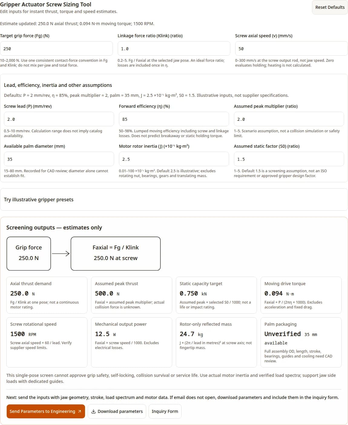
Gripper Actuator Screw Sizing Tool
Edit inputs for instant thrust, torque and speed estimates.
10–2,000 N. Use one consistent contact-force convention in Fg and Klink; do not mix per-jaw and total force.
0.2–5. Fg / Faxial at the selected jaw pose. An ideal force ratio; losses are included once in η.
0–300 mm/s at the screw output rod, not jaw speed. Zero evaluates holding; heating is not calculated.
Lead, efficiency, inertia and other assumptions
Defaults: P = 2 mm/rev, η = 85%, peak multiplier = 2, palm = 35 mm, J = 2.5 ×10⁻⁶ kg·m², S0 = 1.5. Illustrative inputs, not supplier specifications.
0.5–10 mm/rev. Calculation range does not imply catalog availability.
50–98%. Lumped moving efficiency including screw and linkage losses. Does not predict breakaway or static holding torque.
1–5. Scenario assumption, not a collision simulation or safety limit.
15–80 mm. Recorded for CAD review; diameter alone cannot establish fit.
0.01–100 ×10⁻⁶ kg·m². Default 2.5 is illustrative; excludes rotating nut, bearings, gears and translating mass.
1–5. Default 1.5 is a screening assumption, not an ISO requirement or approved gripper design factor.
Try illustrative gripper presets
Hypothetical scenarios, not tested products or motor specifications.
Default example — estimates only
Axial thrust demand
250.0 N
Fg / Klink at one pose; not a continuous motor rating.
Assumed peak thrust
500.0 N
Faxial × assumed peak multiplier; actual collision force is unknown.
Static capacity target
0.750 kN
Assumed peak × selected S0 / 1000; not a life or impact rating.
Moving drive torque
0.094 N·m
Faxial × P / (2πη × 1000). Excludes acceleration and fixed drag.
Screw rotational speed
1500 RPM
Screw axial speed × 60 / lead. Verify supplier speed limits.
Mechanical output power
12.5 W
Faxial × screw speed / 1000. Excludes electrical losses.
Rotor-only reflected mass
24.7 kg
J × (2π / lead in metres)² at screw axis; not fingertip mass.
Palm packaging
Unverified 35 mm available
Full assembly OD, length, stroke, bearings, guides and cooling need CAD review.
This single-pose screen cannot approve grip safety, self-locking, collision survival or service life. Use actual motor inertia and verified load spectra; support jaw side loads with dedicated guides.
Next: send the inputs with jaw geometry, stroke, load spectrum and motor data. If email does not open, download parameters and include them in the inquiry form.
Published and reviewed: · Inverted Roller Screw · Screening guide, not a qualified actuator design. About the publisher
Key decisions before selecting a gripper screw
Size the complete load path
Convert your jaw-force requirement at each pose. Check the screw, support bearings, guides and jaw pivots separately. More contact points do not establish shock immunity.
SKF roller screws selection guide, pp. 10–15 and 23Compare full assemblies
The inverted layout offers integration options, but the minimum nut OD is only one dimension. Check motor, stroke and guide space before committing to palm actuation.
Rollvis RVI architectureTreat lead as a trade-off
The kinetic-energy model below predicts one-quarter rotor-only reflected mass when lead doubles, at twice the steady moving torque for fixed force and efficiency. It does not prove collision safety.
See the derivation and sensitivity tablePlan retained grip and heat rejection
Backdriving can release a load. Select and test an appropriate brake or retention device; do not infer zero-current holding from fine lead.
SKF roller screws selection guide, pp. 10–15 and 231. Method: one pose, one force convention
The screen uses an ideal linkage force ratio Klink = Fg / Faxial and applies lumped moving losses once through η. If your ratio already includes measured friction, avoid counting the same loss twice. Evaluate multiple poses; do not use a near-toggle high advantage over the entire stroke.

| Output | Equation | Boundary |
|---|---|---|
| Axial force demand, N | Faxial = Fg / Klink | No payload, friction coefficient or acceleration model. |
| Assumed peak, N | Fpeak = Faxial × peak multiplier | An assumed load case, not an impact simulation. |
| Static target, kN | C0,target = Fpeak × S0 / 1000 | Default S0 = 1.5 is illustrative, not an ISO rule. |
| Moving torque, N·m | T = Faxial × (P / 1000) / (2πη) | η as a fraction; excludes acceleration and fixed preload/seal drag. |
| Screw speed, RPM | n = 60v / P | v in mm/s at screw output; P in mm/rev. |
| Mechanical power, W | Pout = Faxial × v / 1000 | Electrical input and stationary copper loss are not calculated. |
| Rotor reflected mass, kg | mrotor = Jrotor × (2π / (P / 1000))² | At screw axis; not total moving or fingertip mass. |
Steady torque is a starting point for motor selection. Add accelerating inertia, preload and guide drag, then check the motor torque-speed curve, drive current, duty cycle and temperature. Input limits are numerical screening ranges, not proof that a corresponding product exists.
2. Compare architectures by the work they must do

| Architecture | Reason to investigate | What to verify | Cost / fit risk |
|---|---|---|---|
| Inverted roller screw | Coaxial integration and axial force transmission. | Nut/motor bearings, reverse torque, stroke, lubrication and jaw guides. | Custom motor and nut integration may add tooling and qualification expense. |
| Miniature ball screw | Assess available components for the required force and precision. | Actual catalog ratings, preload, impact load cases and package. | A complete standard assembly may reduce integration work; compare quotations. |
| Sliding lead screw | Evaluate a simpler nut drive for lower duty or specific retention needs. | Wear, efficiency, temperature and tested reverse behavior. | Lower component complexity can trade against wear and maintenance. |
| Remote tendon drive | Move motor mass out of the palm when distal mass is limiting. | Routing friction, tension, elasticity and wrist/finger coupling. | Cable routing, calibration and replacement access add system work. |
Review the inverted planetary roller screw architecture alongside the complete assembly requirements below.
These are selection hypotheses. No named robot adoption, bandwidth, grip-force ceiling, cable life or zero wrist coupling is claimed without a matching specification and test method. Ask suppliers for complete assemblies under the same jaw geometry, force and duty.
3. Verified component data and the packaging gap
The following rows are transcribed from the cited RVI table, printed page 48. Ca is dynamic capacity, C0a static capacity, and D1 minimum nut external diameter. None is an allowable gripper shock force or a complete actuator OD.
| Model | Ca / C0a (kN) | D1 (mm) | Direct / indirect efficiency |
|---|---|---|---|
| RVI 10.5 × 2 | 13.4 / 20.8 | 24 | 0.87 / 0.85 |
| RVI 12 × 1 | 13.9 / 26.8 | 26 | 0.78 / 0.71 |
| RVI 12 × 2 | 16.5 / 27.1 | 26 | 0.86 / 0.83 |
The cited table does not establish an RVI 8 × 0.5 configuration or a 27–28 mm integrated actuator. Those dimensions and smaller custom options require a current supplier drawing. Catalog efficiencies also do not include your whole gripper linkage.

Check your gripper load case with engineering
Have a jaw drawing and operating load case? Send your force convention, stroke, palm envelope and duty profile for review. Save the tool parameters above to keep the assumptions attached.
Request a gripper drawing review4. Lead and reflected inertia: a reproducible sensitivity check
From v = ωP/(2π) and rotational energy Jω²/2 = mv²/2, the rotor term at the screw axis is m = J(2π/P)² with P in metres. This is an ideal rigid, direct-drive mapping. A motor reduction ratio must be included separately. Wensing et al. provides broader impact-response context; it is not evidence of tested gripper values.
Wensing et al., MIT Cheetah actuator design (2017)| Lead (mm/rev) | Rotor-only reflected mass (kg) | Moving torque (N·m) | Screw speed at 50 mm/s (RPM) |
|---|---|---|---|
| 1 | 98.7 | 0.047 | 3000 |
| 1.5 | 43.9 | 0.070 | 2000 |
| 2 | 24.7 | 0.094 | 1500 |
| 3 | 11.0 | 0.140 | 1000 |
| 4 | 6.2 | 0.187 | 750 |
Total endpoint inertia is pose dependent. For an ideal single output coordinate y with x as screw travel, the screw-axis inertia contribution reflects to y by (dx/dy)². Declare the coordinate and include all moving parts before interpreting fingertip impedance. A lower rotor term alone does not establish safe contact force.
5. Holding force, backdriving and palm temperature
Fine lead does not guarantee self-locking. Manufacturer guidance describes roller screws as generally reversible; if object retention matters during power loss, verify the complete retention mechanism. The moving-efficiency torque formula does not predict static breakaway or holding current.
SKF roller screws selection guide, pp. 10–15 and 23
| Question | Known from the screen | Required evidence |
|---|---|---|
| Will it retain force without power? | Not calculated. | Reverse torque over temperature, power-loss retention and brake/load tests. |
| Can current be reduced after closure? | No fixed reduction is approved. | Required retained force and measured motor torque/current; reduce only while the force requirement is met. |
| Will the sealed palm overheat? | Mechanical power only; no thermal model. | Winding resistance and current convention, hold duty, thermal resistance and stabilized temperature. |
Reducing current reduces motor torque as well as copper loss. Do not prescribe a 30% holding-current step without retained-force testing. Design the winding-to-chassis conduction path, measure winding temperature and qualify the duty profile instead of claiming a universal heat reduction.
6. Keep jaw moments out of the screw load path

| Load | Check | Next action |
|---|---|---|
| Axial screw force | Screw, support bearings, housing shoulders and buckling. | Evaluate the full stroke and peak load spectrum. |
| Offset jaw moment | M = F × offset, with consistent N·m units. | Select guide spacing and moment capacity; do not express moment capacity in N. |
| Transverse force | Guide reaction forces and deflection. | Check alignment, tolerance stack and allowable screw side loading with supplier. |
Contact stress needs geometry, material properties, preload and load sharing. No generic MPa table or “survives a 2.5 kN drop” conclusion is defensible from axial force alone. Compare supplier load ratings, then validate representative impacts separately.
7. Short strokes and maintenance need a duty-specific plan
Record stroke amplitude, dwell, temperature, contamination and torque trends. A gripper that mostly holds or dithers needs a lubrication review; the page does not establish a universal minimum stroke or a relubrication counter.

Choose lubricant, seal compatibility and interval with the screw supplier. Inspect a new installation rather than promising a fixed cycle life; maintenance depends on heat, grease condition and duty.
Curtiss-Wright Actuation technical FAQ8. Worked screening cases — hypothetical, not test results
All cases use J = 2.5 ×10⁻⁶ kg·m² and S0 = 1.5 as assumptions. Speed is at the screw. These show the arithmetic and next decision, not a validated motor, payload or drop-survival specification.
| Case and inputs | Calculated outputs | Next check |
|---|---|---|
| Standard: Fg 250 N, K 1, v 50 mm/s, P 2 mm, η 85%, peak ×2 | Faxial 250 N; T 0.094 N·m; 1,500 RPM; C0,target 0.750 kN. | Check the worst jaw pose, continuous motor torque and full palm CAD. |
| Compact: Fg 80 N, K 0.8, v 60 mm/s, P 1.5 mm, η 85%, peak ×1.8 | Faxial 100 N; T 0.028 N·m; 2,400 RPM; rotor term 43.9 kg. | A 25 mm envelope remains unverified; compare remote actuation if integration fails. |
| Heavy: Fg 500 N, K 1.2, v 40 mm/s, P 2 mm, η 88%, peak ×2.5 | Faxial 416.7 N; T 0.151 N·m; C0,target 1.563 kN. | Grip force alone does not prove tote payload; add friction, orientation and acceleration. |
| Fast: Fg 150 N, K 1, v 120 mm/s, P 3 mm, η 90%, peak ×2.2 | Faxial 150 N; T 0.080 N·m; 2,400 RPM; Pout 18 W. | Add acceleration torque, thermal duty and object-contact control. |
Reproduce the default software screen
9. Qualification and procurement risks

| Risk | Consequence | Mitigation / alternative |
|---|---|---|
| Mistaking C0a for impact survival | False confidence in drop recovery or precision. | Validate impact loads and post-test torque/backlash; use compliant stops or a different architecture if required. |
| Custom palm integration | Unbudgeted bearings, cooling, tooling and inspection. | Request a complete BOM and prototype quote; compare standard ball-screw or remote-drive assemblies. |
| Too little palm space | Insufficient guide, stroke or motor clearance. | Submit a full CAD envelope; move motors to forearm if distal packaging dominates. |
| Unqualified hold or human contact | Dropped object or excessive contact force. | Define retention and risk-assessment requirements; test sensing, stop behavior and power-loss cases. |
| Unknown wear life | Unexpected backlash and maintenance downtime. | Specify acceptance criteria, duty-cycle endurance and service access before sourcing. |
ISO 3408-5 covers ball-screw rating calculations, while ISO/TS 15066 addresses collaborative industrial robot systems. Neither public scope turns this single-pose estimate into an approved roller-screw design or a safe human-contact force limit.
10. Gripper actuator screw FAQ
Inputs and interpretation
What grip-force convention should I use?
Use the contact-force convention defined by your jaw mechanism, consistently in both Fg and Klink. Per-jaw normal force and the sum of two jaw forces are not interchangeable. The screen cannot derive a payload from grip force without friction and acceleration data.
Is the speed input jaw speed or screw speed?
It is axial speed of the screw output rod. Convert measured jaw speed using the linkage Jacobian at the same pose. The force ratio alone does not define every jaw coordinate or opening-speed convention.
Does the static target predict collision survival?
No. It multiplies the assumed axial demand by a chosen peak multiplier and static factor. Actual collision force requires impact velocity, effective mass, contact stiffness, damping and load-path analysis.
Can I use zero speed?
Yes. It represents static holding with zero mechanical output power. Motor copper loss can continue; holding torque, brake operation and winding temperature require separate verification.
Architecture and packaging
Why consider an inverted roller screw for a biped robot gripper?
It can support a coaxial layout with a smooth translating output shaft. Whether it saves space depends on the motor, support bearings, anti-rotation device and guides; compare complete CAD assemblies.
Does a fine lead make a roller screw self-locking?
Do not assume so. Manufacturer guidance describes roller screws as generally backdrivable. Verify reverse efficiency and breakaway torque for the actual assembly; specify a validated retention mechanism when loss of power could release the object.
Does 35 mm of palm diameter guarantee a fit?
No. The tool records the envelope for review. Motor stator, rotor, nut, bearings, guides, wall thickness, wiring, cooling, axial length and stroke must all fit.
Can the screw carry jaw bending moments?
Use a separate guide and verify its load and moment ratings, alignment and deflection. A screw drive is intended to transmit axial load; it should not substitute for a jaw guide.
Dynamics and reliability
Is reflected mass the actual fingertip mass?
No. The displayed term is motor rotor inertia reflected to the screw axis. Total endpoint inertia also includes the rotating nut, gearing, translating parts and the pose-dependent linkage Jacobian.
Is 2–3 mm/rev the optimum lead?
There is no universal optimum. At a fixed rotor inertia, doubling lead quarters the rotor-only reflected mass and doubles the ideal load torque. Check speed, actual motor torque-speed limits, available leads and required grip control.
Can I reduce holding current to 30% automatically?
Only if testing confirms the required retained force or a qualified mechanical retention mechanism carries the load. Current reduction also reduces available motor torque; a fixed percentage can release an object.
How often should the screw be lubricated?
Ask the supplier using the actual stroke, dwell, temperature, contamination and load history, then inspect lubricant and torque trend. No universal Smin = 2P rule or five-million-cycle maintenance interval is established here.
Evidence and procurement
Are these tested robot-hand performance claims?
No. The worked cases are arithmetic examples. Named robot benchmark force, bandwidth, drop survival and maintenance-life figures are not asserted without matching primary evidence.
Does ISO 3408-5 specify the tool default safety factor?
No. Its public scope addresses ball-screw rating and life calculations. The default S0 = 1.5 is an editable screening assumption to be replaced by the selected supplier and application design criteria.
Can this calculator establish human-contact safety?
No. A robot application needs a suitable risk assessment, sensing and control strategy, and validation. A component static rating or a single pinch-force number cannot establish collaborative safety.
What should I send for a quotation?
Download the tool inputs and estimates; include jaw drawings, force convention, pose-dependent linkage data, stroke, speed profile, load spectrum, motor data, duty cycle, environment, life target and prototype or series quantity. Use the inquiry form if a local email client is unavailable.
11. Sources, dates and evidence limits
Links and quoted catalog rows were checked November 9, 2026. Catalog publication versions are identified below; verify current drawings and operating limits before procurement. Calculated examples are explicitly separated from manufacturer data.
| Primary source | Used for | What it does not establish |
|---|---|---|
| Rollvis RVI tables, printed p. 48 (PDF p. 1) | Three catalog rows below: load ratings, minimum nut diameter and forward/reverse efficiency. | May 2024 URL version. Component data, not a complete motorized gripper or impact qualification. |
| Rollvis RVI architecture | Rollers operate inside a threaded tube with a smooth output shaft. | No guaranteed palm OD, motor integration, length reduction or named robot deployment. |
| SKF roller screws selection guide, pp. 10–15 and 23 | Load-rating distinctions, backdriving, lubrication and external guidance. | General roller-screw guidance; supplier approval is needed for the selected inverted assembly. |
| Curtiss-Wright Actuation technical FAQ | Maintenance intervals depend on heat, lubricant condition and duty; inspect new applications. | No universal gripper cycle-life or relubrication interval. |
| Wensing et al., MIT Cheetah actuator design (2017) | System-level relationship between low reflected inertia, backdrivability and impact response. | Legged-robot research, not a tested gripper. The linear screw formula here is derived from kinetic energy. |
| ISO 3408-5:2006 — public scope | Ball-screw load-rating and operational-life calculation scope. | Does not establish a mandatory S0 = 1.5 for roller-screw grippers. |
| ISO/TS 15066:2016 — public scope | Collaborative industrial robot systems and their working environments. | The screen does not assess compliance or supply a universal safe pinch-force threshold. |
Public evidence is insufficient here to compare named humanoid hands by force, bandwidth, wrist crosstalk or service life. There is also no validated generic Hertz-stress table, universal lubrication-stroke threshold, minimum complete actuator OD or drop-survival guarantee.
Send a gripper drawing and load case for review
Include the downloaded parameters, force convention, jaw pose and linkage, stroke, envelope, load history, motor inertia and torque-speed curve, hold duty, life target, environment and quantity. Confirm the complete actuator and guide arrangement before ordering.