
Robotics application · Screening tool and engineering reference
Biped Robot Forearm Actuator Screw
Estimate screw force, torque, speed and mechanical power.
Forearm Kinematic Screen
Forearm linear actuators drive wrist pitch/yaw linkages through perpendicular moment arms. Enter your joint target, linkage distance, and lead to check drive torque and motor speed.
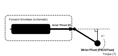
Static relation: Joint torque T = F × r⊥. Check r⊥ across total wrist sweep.
Sizing Scope & Boundaries
This calculator evaluates steady-state kinematics for a single wrist pose. Final actuator engineering requires fatigue life (L10h), thermal dissipation in enclosed arms, radial bearing isolation, and peak impact ratings.
Forearm Actuator Screw Screening Calculator
All five inputs are required. Results update when the calculator is ready. Ranges below are limits of this screening tool, not industry limits.
0–150 N·m at one pose. Use an equivalent single-actuator torque; coupled wrists require a Jacobian.
0.1–120 mm from pivot to actuator line of action. Check the minimum across the full stroke.
0–600 mm/s at the same pose and load. Zero screens a static hold.
0.1–25 mm/rev. Axial travel per revolution; use the selected screw drawing.
1–100%. Default 88% is an illustrative assumption; obtain model-specific efficiency under load.
Try illustrative input presets
Screening Conversion Results
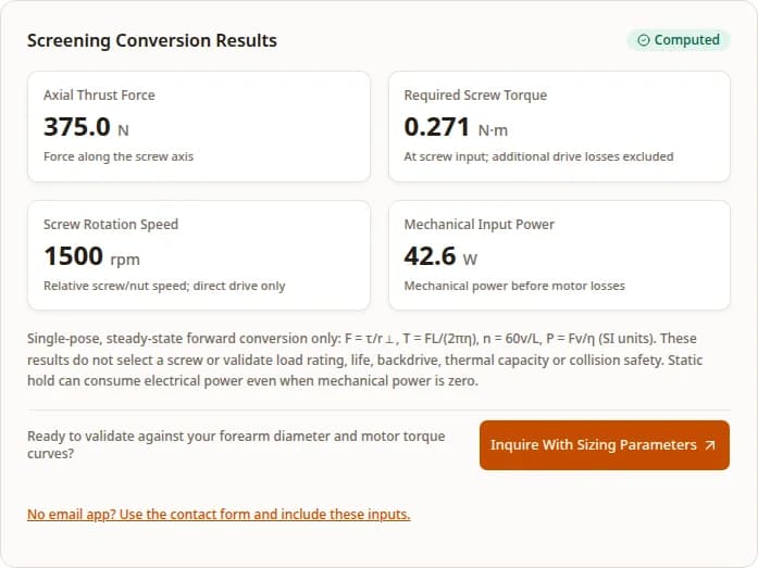
Default exampleSingle-pose, steady-state forward conversion only: F = τ/r⊥, T = FL/(2πη), n = 60v/L, P = Fv/η (SI units). These results do not select a screw or validate load rating, life, backdrive, thermal capacity or collision safety. Static hold can consume electrical power even when mechanical power is zero.
Ready to validate against your forearm diameter and motor torque curves?
Inquire With Sizing ParametersWorked example: convert one forearm pose
Reproducing the calculator's default inputs: 15 N·m wrist torque, 40 mm effective moment arm, 100 mm/s linear speed, 4 mm lead, and 88% estimated screw efficiency.
- Axial Thrust Force
- 375.0 N
15 N·m ÷ 0.040 m = 375.0 N
- Screw Drive Torque
- 0.271 N·m
375.0 N × 0.004 m ÷ (2π × 0.88) ≈ 0.271 N·m
- Screw Rotational Speed
- 1500 rpm
100 mm/s ÷ 4 mm/rev × 60 = 1500 rpm
- Estimated Input Power
- 42.6 W
375.0 N × 0.100 m/s ÷ 0.88 ≈ 42.6 W
Note: This calculation establishes single-pose steady-state operating values. Motor sizing must also account for acceleration torque (J·α), winding I²R thermal dissipation inside the forearm, and bearing preload drag.
Key conclusions for biped robot forearm actuator design
Decision statements supported by the reference matrix and explicitly stated calculation assumptions above.
01
Compare complete assemblies for fit
A coaxial arrangement is a candidate for compact integration. The RVi architecture supports this option, but nut diameter is not assembled actuator OD.
02
Moment Arm Variations Dominate Peak Thrust Demand
F = τ/r⊥ is a single-actuator relationship. The reproducible scenarios show how halving the assumed moment arm doubles thrust. Use a Jacobian for a coupled wrist.
03
Catalog capacity is not impact qualification
The supplier table provides model-specific Ca and C0a. Neither proves a universal advantage over a ball screw or survival of a specified shock cycle.
04
Reflected Inertia Governs Force Transparency & Bandwidth
At fixed rotating inertia the ideal linear mass scales as 1/L². The assumed-inertia comparison also shows increasing torque demand with lead. Measure actual backdrive and bandwidth before making a compliance claim.
Forearm actuator packaging: evaluate coaxial integration
Compare a coaxial arrangement against complete ball screw, rotary and tendon alternatives. Fit depends on the full assembly.
Inverted Roller Screw Coaxial Integration
Conceptual integration of a motor rotor and rotating nut. The translating output is smooth in the cited Rollvis RVi design. Actual roller and timing-ring motion must follow the selected supplier drawing.
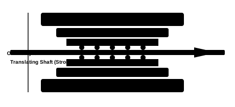
One possible coaxial integration. Nut, motor, guides and bearings determine complete size and mass; no dimensions are implied.
Envelope comparison: request the missing dimensions
Qualitative comparison, not a measured size or mass ranking.
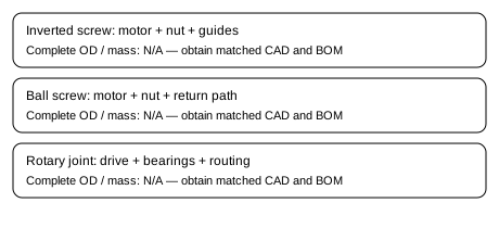
Use identical load, stroke, cooling and life requirements. An isolated nut dimension cannot rank complete wrist modules.
Coaxial integration: check the complete assembly
An inverted roller screw can be integrated with a hollow motor rotor, but the nut is not inherently a motor rotor. Rollvis describes rollers moving inside a threaded nut with a smooth output shaft. Bearings, anti-rotation guidance, motor and housing still require design. See the Rollvis RVi architecture. Check these three integration questions:
- Complete radial envelope:Include stator, bearings, guides, walls and wiring. A nut diameter alone does not establish actuator or limb diameter.
- Mass distribution:Placing motors toward the elbow can reduce distal inertia. Verify actual component locations and mass in assembly CAD.
- Backlash and preload:Specify acceptable reversal error. Preload can reduce play while increasing drag and heat; direct drive does not imply zero backlash.
Published screw and module references: known and unknown
Checked October 28, 2026. Screw reference diameters and nut dimensions are distinct from complete actuator dimensions. These references are not a product selection from the calculator.
| Screw Model / Nominal Ø | Published lead | Dynamic Ca | Static C0a | Peak Thrust | Complete actuator OD / nut dimension | Total Mass | Stroke Range | Target Application |
|---|---|---|---|---|---|---|---|---|
| RVI 10.5 × 2 | 2 mm/rev | 13.4 kN | 20.8 kN | N/A: screw only | N/A; nut D1 = 24 mm | N/A: not published here | N/A: drawing needed | D = 10.5 mm reference diameter. Verify shaft and motor envelope separately. |
| RVI 12 × 1 | 1 mm/rev | 13.9 kN | 26.8 kN | N/A: screw only | N/A; nut D1 = 26 mm | N/A: not published here | N/A: drawing needed | Compare low-lead speed, measured backdrive and preload; no payload inference. |
| RVI 12 × 2 | 2 mm/rev | 16.5 kN | 27.1 kN | N/A: screw only | N/A; nut D1 = 26 mm | N/A: not published here | N/A: drawing needed | Same nominal reference family; lead changes efficiency and load ratings. |
| HJL08 module | 3.5 mm/rev | N/A: not stated | N/A: not stated | 600 N maximum | 49 mm maximum; length 139.9 mm | 500 g | 38 mm maximum | Published inverted-screw module reference; verify mounting and simultaneous operating envelope. |
Sources: Rollvis RVI table, printed page 48 and Techrobots HJL08. Ca and C0a are screw catalog capacities, not motor-limited thrust. N/A means the cited source does not establish that assembly value. Confirm a current drawing and operating conditions with the supplier.
Wrist Kinematics & 2-DOF Parallel Push-Pull Mechanism
How dual linear actuators in the forearm coordinate to actuate wrist Pitch and Yaw degrees of freedom with non-linear moment arms.
2-DOF Parallel Push-Pull Wrist Kinematics (Pitch & Yaw)
Dual linear actuators embedded in the forearm actuate a gimballed wrist platform via universal pushrods.
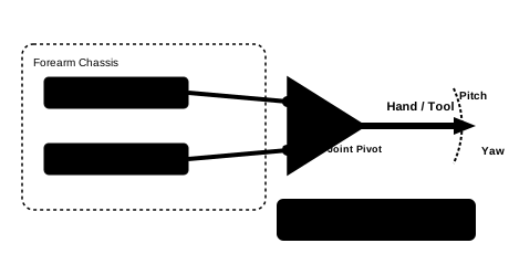
*Illustrative symmetric neutral-pose arrangement. Coordinate mapping, force sharing and workspace limits depend on actual linkage geometry.
Kinematic Formulation & Jacobian Mapping
One possible wrist design uses a parallel 2-SPU + U (Spherical-Prismatic-Universal with central Universal pivot) linkage architecture. The linear actuators lie fixed or pivoted in the forearm base, and their pushrods connect to horn offsets on the wrist gimbal platform. This is an illustrative architecture, not a claim of market prevalence.
Rod vector and length: l_i = R · p_ei0 + p_c - b_i; q_i = ‖l_i‖
Velocity Mapping: dq/dt = J(θ) · dθ/dt
Torque Mapping: τ_wrist = J^T · F_thrust
Here J is the 2×2 derivative of actuator lengths with respect to the chosen pitch/yaw coordinates θ. By virtual work, τ_wrist = JTF; solve the coupled system at every pose.
Unison Stroke (Pitch): In a symmetric neutral-pose layout, matched strokes can produce pitch. Direction depends on attachment geometry.
Differential Stroke (Yaw): Opposed strokes can produce a second rotation near the neutral pose. Away from it, solve the full coupling.
Moment Arm Degradation: A cosine relation applies only to particular planar geometry. Derive actual moment arms from CAD and check singularities; this single-actuator tool does not allocate two-axis loads.
Reflected Inertia & Dynamic Bandwidth: The N² Transmission Law
How lead changes ideal reflected mass and drive demand. Contact response also depends on geometry, friction and control.
Calculated reflected mass versus lead
Inverse-square relationship for an assumed J = 2.5 × 10⁻⁶ kg·m². No measured safety or backdrive ranking.
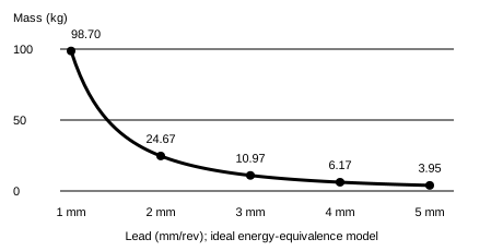
Larger lead reduces this ideal inertia term but increases torque for the same thrust. Include the actual rotor, rotating nut and drive inertia, friction and control behavior.
The Physics of Apparent Mass: m_ref = J · (2π / L)²
Equating rotating energy ½Jω² with linear energy ½mv² and using ω = 2πv/L gives the ideal reflected mass below, with L in meters. Wensing et al. (2017) studies the broader role of transmission inertia in robot interaction; this screw example is our own derivation.
For an assumed rotating inertia J = 2.5 × 10⁻⁶ kg·m², a 1.0 mm lead creates an apparent mass of 98.7 kg at the linear output. Increasing lead to 4.0 mm gives 6.17 kg for the same assumed inertia, a 93.75% reduction in this ideal term. This is derived from energy equivalence, not measured hand apparent mass. Linkage geometry, moving mass, friction and control response still determine contact behavior.
| Screw Lead (L) | Transmission Ratio (2π/L) | Reflected Mass (m_ref) | Screw input torque at 375 N, η = 88% | Relative speed at 100 mm/s |
|---|---|---|---|---|
| 1.0 mm | 6283 rad/m | 98.70 kg | 0.068 N·m | 6000 rpm |
| 2.0 mm | 3142 rad/m | 24.67 kg | 0.136 N·m | 3000 rpm |
| 3.0 mm | 2094 rad/m | 10.97 kg | 0.203 N·m | 2000 rpm |
| 4.0 mm | 1571 rad/m | 6.17 kg | 0.271 N·m | 1500 rpm |
| 5.0 mm | 1257 rad/m | 3.95 kg | 0.339 N·m | 1200 rpm |
Assumed J = 2.5 × 10⁻⁶ kg·m², η = 88%, thrust = 375 N, speed = 100 mm/s. Torque uses the forward conversion model; breakaway and holding behavior require separate measurements. Actual rotor, nut and transmission inertia must replace assumed J.
Transverse Load Isolation: Protecting Screws from Bending Moments
Design an axial screw load path and route transverse loads through guides and structural bearings. Check residual side loads and misalignment against supplier limits.
Transverse Load Isolation: Radial Load Bypass
Bending moments (Mb) and shear loads (F_side) are shunted directly into the forearm chassis via linear guides, isolating the screw nut.
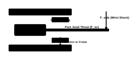
Intended load path: guides carry transverse force and bending. Alignment, compliance and tolerances can leave residual screw side loads; verify these in the assembled mechanism.
Contact Kinematics: Line Contact vs. Point Contact
Conceptual ball and roller contact regions. Geometry and material details are omitted; use model-specific ratings for selection.
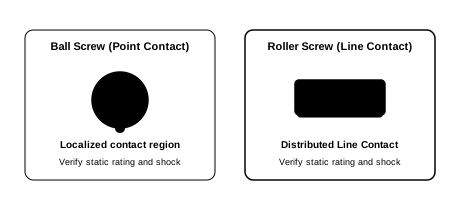
Conceptual contact geometry only. Both architectures require model-specific load ratings and impact qualification; this sketch establishes no shock multiplier or damage-free operating envelope.
| Guidance Architecture | Capacity verification | Friction Drag | Radial Clearance | Mass Penalty | System Tradeoff |
|---|---|---|---|---|---|
| Linear ball spline | Select from model force and torque ratings | Measure preload and seal drag | Supplier preload options | CAD / BOM required | Compact combined guidance and anti-rotation; precision raceways and preload add cost. |
| Dual miniature guide rails | Check forces (N) and moments (N·m) | Measure assembled friction | Check preload and rail alignment | CAD / BOM required | Wide bearing spacing can support bending; rails and alignment consume radial space. |
| Composite or bronze bushings | Check pressure, speed and bearing spacing | Material and lubrication dependent | Fit, temperature and wear dependent | CAD / BOM required | Simple packaging may reduce cost; evaluate stick-slip and clearance under reversal. |
Thermal Dissipation & Duty Cycle Sizing in Sealed Forearm Enclosures
Operating high-density linear actuators inside sealed composite forearm skins requires rigorous thermal modeling to prevent winding insulation breakdown and grease degradation.
Forearm Actuator Thermal Dissipation Network
Conduction path from motor stator copper losses (I²R) through aluminum thermal bridging to the outer limb structure.
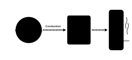
Illustrative heat path, not a temperature prediction. Interface resistance, shell construction and ambient cooling determine the actual thermal response; validate against component-specific limits.
RMS Continuous Sizing Formula: F_rms vs F_peak
Motor copper losses scale with current squared. With fixed torque constant, lead, efficiency and negligible friction, force can proxy current. Changing linkage geometry, friction, acceleration and speed-dependent losses require an actual current and speed profile. RMS force is only a first-pass summary:
No universal percentage of peak thrust or temperature ceiling establishes continuous operation. Include loaded static dwell even though its mechanical power is zero. Confirm the motor thermal model, mounting path, ambient conditions and measured winding temperature before accepting the duty cycle.
| Design Variable | Required input / known boundary | Physical System Consequence |
|---|---|---|
| Heat path through enclosure | Unknown until stack-up and interfaces are defined | Model conduction from winding through chassis and shell, including contact resistance. Validate at worst ambient. |
| Continuous current / thrust | Use measured cycle and motor thermal data | No universal continuous-to-peak thrust ratio. Include static dwell, acceleration, speed-dependent losses and cooling. |
| Lubrication and short strokes | Supplier-approved grease and service interval | Check compatibility, seal drag and grease distribution at the actual oscillation amplitude. Confirm any exercise routine with the supplier. |
| Allowable temperatures | Component-specific limits; not calculated here | Use the lowest applicable motor, encoder, magnet, seal and lubricant limit with a design margin. Instrument a representative enclosure. |
From forearm requirement to engineering verification
Connecting physical robot constraints to specific engineering checks and tests.
| Design Question | Physical Implication | Verification Action |
|---|---|---|
| Radial envelope | Two circular bodies cannot be assumed to fit from limb width alone; walls, guides and wiring consume space. | Check complete cross-section CAD throughout stroke, cable bend radius, service access and actual motor OD. |
| Wrist torque across the workspace | Single-pose moment arms and two-axis load sharing vary with geometry. | Sweep the Jacobian, loads and velocities across all required poses. Track minimum moment arm and peak drive demand. |
| Shock and static load | Catalog C0a is not proof of impact survival or a prescribed universal safety factor. | Define shock spectrum, allowable deformation, supports and supplier-approved static margin, then run the agreed impact test. |
| Continuous operation | Peak force and zero-speed mechanical power do not determine allowable holding time. | Use current / speed duty cycle, winding thermal model, actual enclosure and temperature measurements. |
Compare forearm actuator architectures by real engineering metrics
Tradeoffs between competing actuation technologies for humanoid distal limbs.
| Architecture | Application Fit | Tradeoff to Evaluate |
|---|---|---|
| Inverted roller screw with coaxial motor | Candidate when a translating output and concentric packaging suit the mechanism. | Obtain a complete motor, nut, bearing and guide design. Compare custom machining, inspection and preload costs; inspect the actual shaft architecture. |
| Miniature ball screw | Candidate when catalog availability, efficiency and cost meet the design requirements. | Check model-specific nut OD, return circuit, backlash and static rating; diameter alone cannot rank shock resistance. |
| Rotary wrist actuator | Candidate for direct joint rotation without a linear linkage. | Check distal mass, rotary bearing loads, reduction friction and cable routing against workspace and response needs. |
| Remote cable / tendon drive | Candidate when moving motor mass toward the elbow or torso is valuable. | Test routing, tension, compliance, friction, fatigue and maintenance over the elbow workspace. |
Reproducible forearm actuator sizing scenarios
Hypothetical calculations, not customer deployments or measured endurance tests. Reproduce each scenario in the calculator above.
Scenario 1: nominal wrist pose
Challenge: Assume 15 N·m, 40 mm moment arm, 100 mm/s, 4 mm lead and 88% efficiency.
Calculation: F = 15 / 0.040 = 375 N; T = 375 × 0.004 / (2π × 0.88) = 0.271 N·m; n = 1,500 rpm.
Interpretation and next action: Mechanical input is 42.6 W. Next, compare a supplier torque-speed curve and complete envelope; no particular screw has been selected.
Scenario 2: reduced moment arm
Challenge: Keep Scenario 1 torque, speed, lead and efficiency, but reduce the perpendicular moment arm to 20 mm.
Calculation: F = 750 N; T = 0.543 N·m; n = 1,500 rpm; P = 85.2 W.
Interpretation and next action: Halving the moment arm doubles thrust, torque and power in this model. Sweep actual geometry instead of assuming a universal wrist-angle cutoff.
Scenario 3: loaded static dwell
Challenge: Use Scenario 1 inputs with linear speed set to zero during a stationary grasp.
Calculation: F = 375 N and load-dependent screw torque remains 0.271 N·m. Speed and mechanical power become zero.
Interpretation and next action: Electrical loss is unknown. Measure holding current and winding temperature and evaluate the brake; zero mechanical power does not establish safe dwell time.
Evidence and methodology
Calculations utilize fundamental linkage statics and screw kinematics. Cited technical sources provide boundaries; none constitutes an off-the-shelf guarantee for unverified robot assemblies. First recorded October 28, 2026; technical review October 28, 2026. Prepared by Inverted Roller Screw. Numerical examples document this tool, not physical testing or customer results.
Next technical review: April 28, 2027, or sooner if supplier specifications or the calculation method change.
Rollvis RVi product architecture
Checked October 28, 2026
Describes rollers inside a threaded nut and a smooth output shaft, with customizable integration. Supports considering an inverted arrangement for a constrained envelope.
Limit: Product-family features do not establish assembled actuator diameter, mass, zero backlash or a forearm-specific preference.
Rollvis RVI data tables — printed page 48 (PDF page 1)
Checked October 28, 2026; supplier-hosted table version in May 2024 URL
Supplies model-specific reference diameter D, lead P, Ca, C0a, efficiency, backlash and nut dimension D1. The reference matrix below transcribes selected rows.
Limit: D is not the smooth output-shaft diameter. D1 is a minimum nut dimension, not a complete motor housing. Catalog capacities are not continuous actuator thrust or a shock-life guarantee; obtain a current drawing.
Techrobots HJL series — HJL08 module
Checked October 28, 2026; no publication date shown
The HJL08 specification table lists an inverted planetary roller screw, 3.5 mm lead, 600 N maximum thrust, 300 mm/s maximum speed, 38 mm maximum stroke, 49 mm maximum diameter, 139.9 mm maximum length and 0.5 kg mass.
Limit: Maximum values are not established as simultaneous continuous operation. Screw Ca and C0a are not supplied. Published dimensions still require a current drawing, mounting details and a forearm workspace check.
Wensing et al. — Proprioceptive Actuator Design in the MIT Cheetah
Published 2017; checked October 28, 2026
Research on transmission inertia, backdrivability and impact response in a legged robot. Motivates evaluating reflected inertia and controller behavior together.
Limit: This is a geared leg study, not a forearm screw validation. The linear mass table is our ideal energy-equivalence calculation with an assumed rotor inertia; it does not predict contact safety.
Theoretical kinematic equations provide exact geometric conversions. However, actual thermal rise in sealed composite forearms and backdrive friction under preloaded roller assemblies must be validated on physical dynamometer test fixtures.
Risks and mitigations
Address these critical failure modes in CAD and test benches before committing to production tooling.
Side load or misalignment
Route transverse loads through guides and bearings; check stiffness, tolerances and residual loads with the screw supplier.
Near-singular linkage geometry
Sweep the actual mechanism Jacobian and enforce validated workspace limits. No universal 20 mm minimum applies.
Heat during motion and static hold
Use a measured current profile and component thermal limits; validate worst-case duty in the intended enclosure.
Short-stroke lubrication
Confirm grease, oscillation amplitude and service routine with the supplier; inspect wear during endurance testing.
Custom integration cost
Quote machining, preload setting, guides, bearings, inspection and replacement access. Compare catalog ball screw and rotary alternatives before tooling.
Evidence boundary: Calculated force and speed values reflect single-point kinematics. Real-world reliability depends on thermal dissipation paths in sealed shells, harmonic vibration resonance, and contamination protection.
Biped robot forearm actuator FAQ
Direct engineering answers for sizing, selection, and supplier collaboration.
When is an inverted roller screw worth considering for a biped robot forearm?
Consider it when a coaxial motor and translating output can meet your envelope and thrust requirements. Rollvis documents an internally threaded nut with a smooth output shaft. Compare complete actuator CAD, cost, preload and thermal performance against a ball screw, rotary drive or tendon system; no architecture wins every constraint.
How do two forearm actuators drive wrist pitch and yaw?
In a symmetric parallel linkage, coordinated extension and differential extension can produce different wrist rotations near the neutral pose. Actual axis coupling and load sharing depend on attachment geometry and posture. Use the full mechanism Jacobian; the single-actuator screen does not solve a coupled two-axis wrist.
How do I convert wrist joint torque into linear screw thrust?
For one equivalent actuator at a known pose, F = joint torque divided by the perpendicular moment arm in meters. At 15 N·m and 40 mm, F = 375 N. Repeat across the stroke and motion cycle; add inertia, preload, friction and external load cases before selection.
Can the forearm roller screw support wrist bending and side loads directly?
Provide a separate load path for transverse force and bending through guides, splines and structural bearings. Check residual misalignment and permitted side loads with the screw supplier. A schematic axial load path does not prove zero bending in an assembled mechanism.
Does a larger screw lead guarantee backdrivability or safe contact?
No. At fixed rotating inertia, the ideal reflected linear mass scales with the inverse square of lead. Backdrive also depends on helix geometry, friction, preload, seals, motor cogging and the controller. Measure breakaway force, control response and impact behavior on the assembled actuator.
Can zero mechanical power during a static hold mean zero motor heating?
No. P = Fv is zero at zero speed, but a motor maintaining torque may still draw current and generate copper heat. Verify winding temperature, holding duration and brake behavior in the actual forearm enclosure. This screen does not calculate electrical input or thermal limits.
Prepare a forearm actuator review
Submit your forearm envelope constraints (OD and maximum length), stroke requirement, wrist torque curve, peak and continuous duty cycle, target weight budget, and operating environment to our engineering team for custom inverted roller screw sizing and drawing review.