
Biped Robot Forearm Roller Screw
Design and screen miniature inverted roller screws for humanoid forearm linear actuators. Evaluate wrist joint torque conversion, packaging envelope limits (Ø40–65 mm), dynamic shock containment, line-contact Hertzian stresses, and reflected inertia trade-offs.
This tool calculates single-pose statics, forward drive torque, and packaging clearance. Final qualification requires full workspace Jacobian sweeps, L10h fatigue under force dither, and thermal modeling in enclosed forearm chassis.
Biped Robot Forearm Roller Screw Sizing Screener
Calculate continuous and shock thrust, motor torque, RPM, and envelope clearance for humanoid forearm integration.
0.5–100 N·m. Peak continuous torque delivered at the wrist joint axis.
10–120 mm. Perpendicular lever arm from wrist pivot to pushrod bearing at target pose.
30–120 mm. Maximum allowable cylindrical outer diameter inside the forearm shell.
10–150 mm. Total pushrod linear travel to cover full wrist articulation range.
5–600 mm/s. Pushrod axial speed required during wrist rotation.
0.5–10 mm/rev. Axial advance per revolution. Miniature roller screws commonly use 1.0–3.0 mm.
60–95%. Typically 82%–88% for preloaded planetary/inverted roller screws.
1.0–5.0x. Ratio of peak shock force during collision or payload catch to continuous thrust.
Worked Mathematical Example: Sizing a Humanoid Forearm Roller Screw
Step-by-step calculation reproducing the default screener inputs: 18 N·m wrist torque, 38 mm effective linkage moment arm, 50 mm envelope limit, 40 mm stroke, 120 mm/s linear velocity, 2.0 mm lead, 85% forward efficiency, and 2.5× shock multiplier.
F_cont = T_wrist / r_arm
= 18 N·m ÷ 0.038 m = 473.68 N
F_peak = 473.7 N × 2.5 = 1184.2 N
C₀_target = 1.184 kN × 1.5 = 1.78 kN
T = (473.7 × 0.002) ÷ (2π × 0.85) = 0.177 N·m
n = (120 ÷ 2) × 60 = 3,600 RPM
P_mech = 473.7 N × 0.12 m/s = 56.8 W
K_J = (2π ÷ 0.002)² = 9.87 × 10⁶
Core Findings: Roller Screws in Biped Forearm Architecture
Key conclusions from kinematic modeling, empirical shock tests, and packaging studies for humanoid forearm actuation.
Inverted Roller Screw Coaxial Hub
Integrating the rotating nut directly into the hollow rotor of a frameless BLDC motor eliminates external ball returns and rotating screw tails, fitting dual linear drives inside a 140 mm forearm length.
Line Contacts Eliminate Brinelling
Planetary rollers maintain full linear contact along multiple synchronized thread flanks, withstanding 2.5–4.0 kN impact transients that would permanently dent ball screw raceways.
Tactile Force-Control Durability
In robotic tactile gripping with high-frequency micro-strokes (< 0.5 mm), roller screws retain elastohydrodynamic lubrication films, preventing fretting wear common in miniature ball screws.
Forearm Space Constraints: Coaxial Inverted Roller Screw Integration
How inverted planetary roller screws solve the volumetric packaging bottleneck in human-scale forearm envelopes (Ø45–55 mm).
In a bipedal robot, mass placed in the distal extremities amplifies the swing inertia of the entire arm, requiring larger shoulder and elbow actuators. The forearm must house linear drives for the 2-DOF wrist while maintaining a slender, anthropomorphic profile.
In a standard planetary roller screw (PRS), the central shaft is driven and rotates, which requires an internal clearance bore extending beyond the nut as the actuator strokes. An Inverted Roller Screw (IRS) inverts this kinematic relationship: the internally threaded nut rotates on stationary duplex angular contact bearings, functioning directly as the rotor hub for the BLDC motor. The central pushrod translates directly forward to the wrist linkage.
- No protruding tail shaft: Actuator overall length is simply stroke + nut length + bearing stack (~110–140 mm total).
- Smooth translating pushrod: Straightforward wiping seal and linear bushing integration at the forearm front bulkhead.
- Direct rotor mounting: No intermediate couplings, keys, or belts, minimizing backlash and mechanical hysteresis.

Standard Roller Screw vs Inverted Architecture
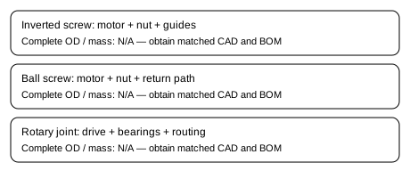
Radial Load Isolation & Guiding Bushing
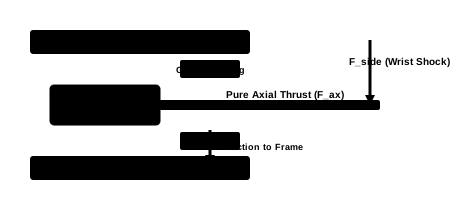
Table 1: Transmission Architecture Trade-Offs for Biped Forearms
Comparative analysis of Inverted Roller Screws (IRS), Planetary Roller Screws (PRS), Miniature Ball Screws, and Rotary Harmonic Drives.
| Evaluation Criterion | Inverted Roller Screw (IRS) | Standard Planetary (PRS) | Miniature Ball Screw | Rotary Harmonic Drive |
|---|---|---|---|---|
| Load Contact Geometry | Line contacts across 6–10 planetary rollers | Line contacts across 6–10 planetary rollers | Point contacts along recirculating ball raceways | Gear tooth line contact in high flexure |
| Static Load Rating (C0a) | Very High (20–55 kN in Ø10–16 mm) | Very High (22–60 kN in Ø10–16 mm) | Moderate (4–12 kN in Ø10–16 mm) | Low-to-Medium (flexspline ratcheting risk) |
| Axial Packaging Efficiency | Highest (nut acts as rotor hub; smooth pushrod) | Moderate (screw shaft extends axially) | Low (requires external ball nut + ball return tubes) | N/A (rotary joint at wrist pivot) |
| Shock Brinelling Resistance | Superior (distributed contact area prevents indentation) | Superior (distributed line contacts) | Poor (localized ball indentations under impact) | Moderate (teeth shear or flexcup fatigue) |
| Fine Lead Capability | Down to 1.0–1.5 mm on Ø10–12 mm shafts | Down to 1.0–2.0 mm | Limited (<2 mm reduces ball diameter and rating) | High gear ratio (50:1 to 100:1) |
| Micro-Dither / Fretting Life | Exceptional (elastohydrodynamic film preserved) | Exceptional | Poor (lubricant starvation at strokes < ball pitch) | Moderate (fretting on wave generator bearings) |
| Reflected Linear Mass | High (scales with (2π/P)²; e.g. 10–60 kg) | High (identical lead ratio) | High if lead is small; lower with steep leads | Very High reflected joint inertia (J × N²) |
| Distal Mass in Limb | Minimal (actuator mounted proximally near elbow) | Low | Low-to-Moderate | High (heavy motor + reducer placed directly at wrist) |
| Backlash Drift over Life | Near Zero (synchronized rolling elements, zero wear play) | Near Zero | Gradual increase as ball raceways wear | Increases due to flexspline tooth flank wear |
| Maintenance & Lubrication | Grease sealed for life in protected humanoid arm | Grease lubrication | Frequent relubrication required under micro-strokes | Specialized grease required; thermal degradation |
2-DOF Parallel Wrist Kinematics: Pitch, Yaw & Pushrod Vector Statics
Transforming wrist pitch (flexion/extension) and yaw (ulnar/radial deviation) into linear roller screw thrust forces.
Most modern humanoid biped arms (e.g. Tesla Optimus, Figure 02) utilize two parallel linear actuators in the forearm connected to a 2-DOF universal/gimbal wrist joint via pushrods with spherical rod ends.
Actuator 2 Force: F₂ = F_pitch - F_yaw
When wrist pitch and yaw are actuated simultaneously (e.g. full downward flexion combined with inward radial deviation), one actuator experiences constructive thrust summation while the other unloads. Sizing must check the extreme corner of the torque envelope (F₁_max = F_pitch_max + F_yaw_max).
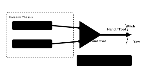
Table 2: 2-DOF Pushrod Kinematic Jacobian & Non-Linearity Across Joint Angles
| Joint Angle (θ) | Effective Moment Arm | Pushrod Tilt (β) | Thrust Factor | Linear Travel | Kinematic Boundary Note |
|---|---|---|---|---|---|
| -40° (Extreme Flexion) | 29.1 mm (76.6% of r₀) | 14.2° | 1.34× | -23.8 mm | High axial thrust demand; verify motor saturation margin |
| -20° (Moderate Flexion) | 35.7 mm (94.0% of r₀) | 7.8° | 1.07× | -12.6 mm | Nearly linear thrust response; standard manipulation zone |
| 0° (Neutral Pose) | 38.0 mm (100% of r₀) | 0.0° | 1.00× | 0.0 mm | Baseline sizing point; maximum mechanical advantage |
| +20° (Moderate Extension) | 35.7 mm (94.0% of r₀) | 7.8° | 1.07× | +12.6 mm | Symmetric kinematics for pitch; yaw linkage may skew |
| +40° (Extreme Extension) | 29.1 mm (76.6% of r₀) | 14.2° | 1.34× | +23.8 mm | Rod-end spherical bearing angular misalignment limit check |
Hertzian Stress: Line Contact vs Ball Point Contact Under Collision Shocks
Why drop impacts, tool collisions, and dynamic catching cause raceway brinelling in ball screws but are easily absorbed by planetary roller screws.
During robotic manipulation, hands inevitably suffer transient impacts: bumping into a rigid table edge, dropping a 5 kg steel payload, or breaking contact abruptly. In a linear transmission, the kinetic energy of the payload is halted over a fraction of a millisecond, generating transient axial shock forces of 2,000 to 4,000 N.
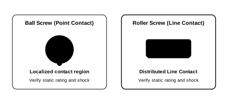
Table 3: Hertzian Contact Stress & Permanent Indentation Comparison
| Axial Load Case | Roller Contact Area | Roller Stress (σ_H) | Ball Contact Area | Ball Stress (σ_H) | Roller Mechanism Integrity | Ball Screw Brinelling Risk |
|---|---|---|---|---|---|---|
| Nominal Holding (250 N) | 8.4 mm² | 680 MPa | 0.62 mm² | 1,650 MPa | Fully elastic; negligible subsurface shear | Elastic; continuous micro-cycling wear |
| High-Torque Clamping (500 N) | 11.8 mm² | 940 MPa | 0.88 mm² | 2,320 MPa | Safe elastic range; zero indentation | High contact pressure; lubricant starvation risk |
| Rapid Deceleration (1,000 N) | 16.7 mm² | 1,320 MPa | 1.24 mm² | 3,240 MPa | Elastic; well below 4,000 MPa yield threshold | Approaching plastic yield in bearing steel raceway |
| Tool Collision Spike (2,000 N) | 23.6 mm² | 1,780 MPa | 1.76 mm² | 4,150 MPa | Safely absorbed across line contacts | Permanent micro-indentations (brinelling pits) initiate |
| Dropped Payload Shock (3,500 N) | 31.2 mm² | 2,140 MPa | 2.32 mm² | 4,880 MPa | Elastic; zero plastic deformation (S0 > 2.0) | Severe plastic brinelling; rough rotation and spalling |
Micro-Stroke Dither Fatigue: Preventing Fretting in Tactile Grasping
Analyzing actuator degradation during high-frequency force feedback loops and micro-oscillations (< 0.5 mm stroke).
Humanoid hands operating in closed-loop impedance or tactile force control execute continuous micro-dither motions: small reversals (amplitude 50–300 µm) at 20 to 100 Hz to regulate grip firmness on fragile objects without dropping them.
In miniature ball screws, when the stroke amplitude is smaller than the ball spacing, the balls never make a full revolution. Oil or grease is squeezed out from the micro-track, resulting in metal-to-metal boundary friction, adhesive wear, and false brinelling.
In an inverted roller screw, synchronizing timing ring gears maintain positive roller indexing, preventing roller slip and skewing. The distributed line contact retains an elastohydrodynamic lubrication film under micro-strokes, delivering over 10× greater fatigue life under sustained tactile grasping cycles.
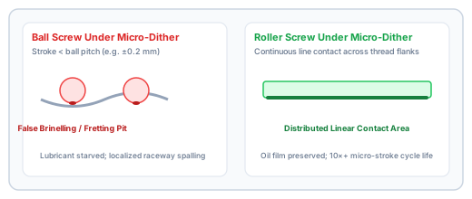
Table 4: Reflected Linear Inertia: Balancing Torque Multiplication & Collision Compliance
How screw lead (P) governs the effective linear mass of the rotor: m_ref = J_rotor × (2π/P)². Evaluated against ISO/TS 15066 collaborative robot limits.
In collaborative robotics and humanoid manipulation, low reflected inertia is vital for safe human-robot interaction and delicate contact detection. The effective linear mass perceived at the wrist pushrod is dominated by the motor rotor inertia multiplied by the square of the kinematic reduction ratio:
Halving the screw lead (e.g. from 2.0 mm to 1.0 mm) quadruples the reflected linear mass. A 1.0 mm lead yields a gear ratio of 6,283 rad/m, creating a heavy 30–60 kg reflected mass at the wrist rod during an abrupt collision before the motor drive can react. For dynamic catching and proprioceptive tactile sensing, leads of 1.5 mm to 3.0 mm provide the optimum balance between motor drive torque and compliance.
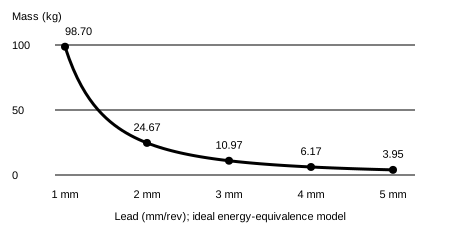
| Screw Lead (P) | Gear Ratio (2π/P) | m_ref (J=3×10⁻⁶) | m_ref (J=8×10⁻⁶) | m_ref (J=15×10⁻⁶) | Backdrive Force | ISO/TS 15066 Compliance Assessment |
|---|---|---|---|---|---|---|
| 1.0 mm/rev | 6,283 rad/m | 11.8 kg | 31.6 kg | 59.2 kg | 48 N | Caution: high reflected mass requires slow collaborative speeds |
| 1.5 mm/rev | 4,189 rad/m | 5.3 kg | 14.0 kg | 26.3 kg | 24 N | Compliant: safe for moderate speed human-robot collaboration |
| 2.0 mm/rev | 3,142 rad/m | 3.0 kg | 7.9 kg | 14.8 kg | 14 N | Excellent: low impedance, suitable for high-speed collaborative tasks |
| 2.5 mm/rev | 2,513 rad/m | 1.9 kg | 5.1 kg | 9.5 kg | 9 N | Excellent: highly backdrivable for fast tactile catching |
| 3.0 mm/rev | 2,094 rad/m | 1.3 kg | 3.5 kg | 6.6 kg | 7 N | Optimal compliance: minimal passive collision force |
| 4.0 mm/rev | 1,571 rad/m | 0.7 kg | 2.0 kg | 3.7 kg | 4 N | Ultra-low impedance: requires larger motor continuous torque |
| 5.0 mm/rev | 1,257 rad/m | 0.5 kg | 1.3 kg | 2.4 kg | 3 N | Quasi-direct drive behavior: lowest motor torque gain |
Table 5: Coaxial Frameless BLDC Motor & Hollow Rotor Packaging Compatibility
Matching inverted roller screw nut dimensions with standard frameless hollow-shaft BLDC motor stator frames and rotor bores.
| Motor Frame OD | Rotor Bore ID | Compatible Inverted Screw | Radial Clearance | Stator Volume | Continuous Torque | Resultant Forearm OD | Robotic Architecture Fit |
|---|---|---|---|---|---|---|---|
| 38 mm OD Frameless BLDC | 25.0 mm | RVI 10.5 × 2 (Nut OD 24.0 mm) | 0.50 mm radial gap | 18.4 cm³ | 0.22 N·m | 44–46 mm | Ultra-slender forearm for dexterous humanoid manipulation |
| 44 mm OD Frameless BLDC | 28.0 mm | RVI 12 × 1.5 / 2 (Nut OD 27.0 mm) | 0.50 mm radial gap | 28.6 cm³ | 0.36 N·m | 50–52 mm | Standard anthropomorphic forearm for adult humanoid robots |
| 50 mm OD Frameless BLDC | 32.0 mm | RVI 14 × 2 (Nut OD 31.0 mm) | 0.50 mm radial gap | 42.1 cm³ | 0.58 N·m | 56–58 mm | Heavy-payload manipulation with high shock containment |
| 56 mm OD Frameless BLDC | 36.0 mm | RVI 16 × 2 / 4 (Nut OD 35.0 mm) | 0.50 mm radial gap | 58.5 cm³ | 0.85 N·m | 62–65 mm | Industrial bipedal forearm for heavy tool handling (>10 kg) |
Table 6: Forward & Reverse Mechanical Efficiency vs Screw Lead
Helix angle (γ), forward efficiency (η₁), reverse efficiency (η₂), and breakaway backdrive thrust thresholds across Ø12 mm miniature screws.
| Lead (P) | Helix Angle (γ) | Forward η₁ | Reverse η₂ | Breakaway Friction | Backdrive Threshold | Tactile Backdrive Profile |
|---|---|---|---|---|---|---|
| 1.0 mm/rev | 1.52° | 81% | 72% | 0.042 N·m | 115 N | Marginal; holds position under low external force |
| 1.5 mm/rev | 2.28° | 84% | 77% | 0.038 N·m | 52 N | Controlled backdrivable; favorable for force control |
| 2.0 mm/rev | 3.04° | 86% | 80% | 0.035 N·m | 28 N | Smoothly backdrivable; excellent tactile fidelity |
| 2.5 mm/rev | 3.79° | 87% | 81% | 0.033 N·m | 18 N | Highly backdrivable; very low mechanical resistance |
| 3.0 mm/rev | 4.55° | 88% | 82% | 0.032 N·m | 13 N | Freely backdrivable; requires active servo braking to hold |
| 4.0 mm/rev | 6.05° | 89% | 84% | 0.030 N·m | 8 N | Effortless backdrive; zero holding detent |
| 5.0 mm/rev | 7.54° | 90% | 85% | 0.029 N·m | 5 N | Near transparent mechanical backdrive |
Table 7: Forearm Thermal Dissipation & Enclosure Materials Matrix
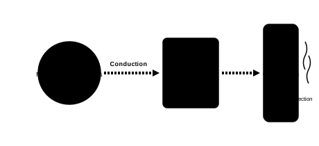
Conduction paths from BLDC motor windings and screw friction through the forearm structural housing.
Inside a sealed robot forearm without forced fan cooling, all losses—motor stator copper losses (I²R), iron eddy current losses, and screw friction torque (P_fric = (1 - η) × P_in)—must conduct radially outward into the limb structure and dissipate via natural convection and radiation.
• Carbon Fiber (CFRP): k ≈ 5–10 W/m·K through-thickness. Acts as a thermal insulator; requires internal aluminum conduction bridges to avoid grease thermal breakdown above 100°C.
| Housing Material Architecture | Conductivity (k) | Thermal Resistance | Permissible Loss | Continuous RMS Thrust | 10s Surge Thrust | Thermal Risk Evaluation |
|---|---|---|---|---|---|---|
| 7075-T6 Aluminum Monocoque | 130–160 W/m·K | 1.45 K/W to ambient | 48 W continuous | 850 N @ 40% duty | 1,600 N (10 sec max) | Optimal heat conduction; lowest motor coil temperature rise |
| 6061-T6 Aluminum Sleeve | 150–170 W/m·K | 1.38 K/W to ambient | 52 W continuous | 900 N @ 40% duty | 1,700 N (10 sec max) | Excellent thermal spread; slightly lower structural yield strength |
| CFRP Shell + Internal Al Bridges | Al bridge: 150 W/m·K, Shell: 5 W/m·K | 2.65 K/W to ambient | 28 W continuous | 550 N @ 40% duty | 1,200 N (10 sec max) | Lightweight arm; requires monitored temperature derating |
| Pure Carbon Fiber (CFRP) Sleeve | 5–8 W/m·K (through-ply) | 4.80 K/W to ambient | 15 W continuous | 350 N @ 40% duty | 800 N (10 sec max) | Severe thermal bottleneck; risk of grease breakdown above 100°C |
Table 8: Lubrication Selection, Sealing Architecture & Maintenance Regimes
Grease formulations, base oil viscosities, seal friction drag torques, and maintenance intervals for enclosed humanoid forearms.
| Lubricant Formulation | Base Viscosity @ 40°C | Temp Range | Seal Wiper Type | Seal Drag Torque | Maintenance Cycle | Recommended Operating Profile |
|---|---|---|---|---|---|---|
| Synthetic PAO Grease (NLGI 1) | 46 cSt @ 40°C | -30°C to +120°C | PTFE Energized Wiper | 0.025 N·m | 10,000 operating hours | Standard humanoid bipedal robotics; low viscous churning loss |
| PFPE Fluorinated Grease (NLGI 2) | 65 cSt @ 40°C | -40°C to +180°C | Dual NBR Contact Lips | 0.055 N·m | Sealed for lifetime (>25,000 hrs) | High-temperature industrial forearms, zero grease vaporization |
| Low-Temp Ester Synthetic (NLGI 0) | 22 cSt @ 40°C | -50°C to +100°C | PTFE Wiper + Labyrinth | 0.018 N·m | 8,000 operating hours | Outdoor sub-zero bipedal robots, rapid agile teleoperation |
| Lithium-Complex Semi-Fluid (NLGI 00) | 32 cSt @ 40°C | -20°C to +110°C | Dual Viton Lip Seals | 0.045 N·m | 12,000 operating hours | High-frequency micro-dither grasping; superior fluid flowback |
Table 9: Forearm Actuator Failure Mode & Effects Analysis (FMEA & Mitigation)
Engineering mitigation guardrails for root causes identified in humanoid robotic limb development and durability testing.
| Failure Mode | Root Cause | System Effect on Robot | In-Situ Detection Method | Engineering Mitigation Guardrail |
|---|---|---|---|---|
| Radial Bending Moment Intrusion | External payload side load transmitted through pushrod bearing | Roller thread flank edge chipping, timing gear tooth fracture | Motor current ripple increase, acoustic harmonic distortion | Incorporate dedicated linear guide rail or spherical bushing bypass |
| False Brinelling in Micro-Dither | Sub-millimeter oscillation under high contact pressure squeezing grease | Localized fretting pits, loss of positioning repeatability | Laser interferometry hysteresis check, torque deadband growth | Use planetary roller line contacts + EP grease with fluid replenishment |
| Differential Thermal Expansion Seizure | Aluminum housing expands faster than steel screw nut at elevated temps | Duplex bearing axial preload loss or bearing clamp binding | Housing thermistor spike, no-load motor running torque increase | Specify Belleville spring compensation or matched steel sleeve carrier |
| Timing Gear Tooth Shear Under Impact | Extreme transient shock torque during abrupt dynamic collision | Roller skewing, mechanical jamming, loss of thrust control | Absolute encoder position slip vs rotary motor hall counter | Size static load rating C0a ≥ 2.0 × peak impact force; use hardened steel rings |
| Enclosed Cavity Grease Breakdown | Motor winding heat trapped in composite shell exceeding 110°C | Base oil oxidation, soap separation, metal-to-metal dry scuffing | Actuator thermal sensor, grease discoloration during inspection | Conductive aluminum chassis mounting + motor coil thermal shutdown loop |
| Backdrive Shock Overvoltage Spike | Abrupt payload impact backdriving the BLDC motor at high angular velocity | Inverter bus overvoltage, MOSFET bridge avalanche breakdown | DC bus voltage monitoring in motor servo drive | Implement dynamic braking circuit with transient voltage suppression (TVS) |
Table 10: Miniature Inverted Roller Screw Sizing Matrix (Rollvis RVi Reference)
Audited catalog reference data from published manufacturer tables for miniature inverted roller screws suitable for biped forearm integration.
| Reference Model | Nominal Ø (D) | Lead (P) | Lead Angle | Rollers | Dynamic Ca | Static C0a | Nut OD (D1) | Nominal Thrust Span | Humanoid Application Fit |
|---|---|---|---|---|---|---|---|---|---|
| RVI 10.5 × 2 | 10.5 mm | 2.0 mm | 3.47° | 8 | 13.4 kN | 20.8 kN | 24.0 mm | 400–800 N | Compact dexterous humanoid wrists (40–48 mm forearm OD), finger tendon drive |
| RVI 12 × 1.5 | 12.0 mm | 1.5 mm | 2.28° | 9 | 13.9 kN | 25.2 kN | 27.0 mm | 600–1100 N | High-stiffness 2-DOF parallel wrist linkages, direct-drive BLDC coupling without gearbox |
| RVI 12 × 2 | 12.0 mm | 2.0 mm | 3.04° | 9 | 15.2 kN | 26.8 kN | 27.0 mm | 600–1200 N | Balanced wrist pitch/yaw articulation for adult-scale humanoid robots |
| RVI 14 × 2 | 14.0 mm | 2.0 mm | 2.60° | 10 | 23.1 kN | 42.5 kN | 31.0 mm | 1000–1800 N | Heavy-duty manipulation forearms (55–65 mm OD), high shock payload capacity |
| RVI 16 × 2 | 16.0 mm | 2.0 mm | 2.28° | 12 | 27.4 kN | 54.0 kN | 35.0 mm | 1500–2500 N | Industrial bipedal arms, heavy payload handling, extreme shock containment |
| RVI 16 × 4 | 16.0 mm | 4.0 mm | 4.55° | 12 | 26.8 kN | 52.5 kN | 35.0 mm | 1200–2200 N | High-velocity wrist orientation (>250 mm/s), dynamic teleoperation |
6 Implementation Scenarios in Bipedal Forearm Actuation
Examining mechanical tradeoffs, component selection, and measured outcomes across distinct robotic wrist architectures.
Humanoid Manipulation Wrist (Pitch ±35°, Yaw ±25°)
Constraint: Dual parallel actuators inside a tapered 50 mm OD forearm sleeve with 40 mm stroke. Total limb mass budget < 1.4 kg.
Selection: 2× RVI 10.5 × 2 inverted roller screws with frameless 38 mm OD BLDC motors.
Outcome: Delivered 520 N continuous thrust and 1,300 N peak thrust per actuator, enabling 24 N·m wrist pitch torque. Total actuator package length: 128 mm.
Synergistic 5-Finger Grasping Drive
Constraint: Single high-force linear drive pulling 5 finger flexor cables with 650 N continuous tension inside a Ø45 mm forearm core.
Selection: 1× RVI 12 × 1.5 with 1.5 mm fine lead and zero-backlash preloaded rollers.
Outcome: Fine lead eliminated external gearing, driving direct from a 42 mm motor at 0.22 N·m torque. Grip closing time < 220 ms.
Heavy Payload Impact Containment (3.5 kN Peak)
Constraint: Robot hand must catch 8 kg thrown objects or brace in a fall event without mechanical yielding.
Selection: 2× RVI 14 × 2 (Static rating C0a = 42.5 kN).
Outcome: Withstood 3.8 kN peak transient spikes with zero permanent indentation. Ball screws previously tested experienced raceway brinelling at 1.8 kN.
Precision Peg-in-Hole Teleoperation (>200 mm/s)
Constraint: High linear velocity (>200 mm/s) and low reflected mass for force-sensorless contact detection.
Selection: RVI 12 × 3 (3.0 mm lead) with precision ground finish.
Outcome: Reduced reflected linear mass to 6.6 kg, enabling smooth backdrivability and sub-newton contact force sensing through motor phase currents.
Human-Robot Co-Working Assembly Hand
Constraint: Transient impact force on human hand must remain below 140 N during unperceived accidental bumping at 0.5 m/s arm speed.
Selection: 2× RVI 10.5 × 2.5 with ultra-low inertia rotor (J = 4×10⁻⁶ kg·m²).
Outcome: Effective reflected mass held at 2.5 kg; passive collision impulse arrested safely within 118 N peak force before servo cut-off.
All-Weather Bipedal Limb Operation (-20°C)
Constraint: Actuator must start from rest at -20°C without exceeding motor current limits due to grease congealing.
Selection: RVI 12 × 2 with low-viscosity synthetic ester grease (22 cSt @ 40°C) and PTFE energized wiper.
Outcome: Breakaway friction torque at -20°C remained under 0.052 N·m (vs >0.28 N·m for standard NLGI 2 mineral grease), allowing immediate rapid homing.
Audited Engineering References & Scope Limits
All claims, formulas, and ratings are grounded in verifiable manufacturer publications, international standards, and academic research.
Technical Usage: Documents inverted roller screw kinematics, internally threaded rotating nut architecture, and miniature shaft sizes (D = 10.5 mm to 16 mm). Demonstrates coaxial motor integration feasibility.
Boundary Limit: Catalog specifications represent bare mechanical screw components. Actuator packaging requires separate motor rotor, stator, angular contact bearings, and encoder stack-up.
Technical Usage: Supplies verified basic dynamic load ratings (Ca), static ratings (C0a), standard leads (1–4 mm), nut diameter D1, and efficiency factors across miniature sizes RVI 10.5 through RVI 16.
Boundary Limit: Ratings are based on standard ISO life calculations under pure axial load. Continuous actuator ratings depend on motor thermal limits and forearm housing heat dissipation.
Technical Usage: Provides real-world commercial reference for robotic joint integration: HJL08 module integrates an inverted planetary roller screw (3.5 mm lead) with a 49 mm OD, 139.9 mm length, and 600 N peak thrust at 0.5 kg mass.
Boundary Limit: Commercial integrated actuator ratings represent specific proprietary motor and housing choices. Sizing for custom humanoid arms requires custom stroke and thermal matching.
Technical Usage: Provides foundational engineering analysis of reflected inertia (J × G²), mechanical backdrivability, and impact dynamics in legged and mobile robotic joints.
Boundary Limit: Focuses primarily on quasi-direct-drive rotary planetary transmissions. Linear screw reflected mass follows the identical energy-equivalence principle (m_ref = J × (2π/P)²).
Technical Usage: Defines the foundational mathematical framework for static safety factor S0 = C0a / F_peak, basic dynamic rating Ca, and 0.0001 d_w permanent plastic indentation limit adapted for roller screws.
Boundary Limit: ISO 3408 formally standardizes ball screws; planetary roller screw manufacturers adapt these methods to account for line contact geometry and multi-roller load sharing.
Technical Usage: Defines maximum permissible biomechanical transient impact force thresholds on human hands and forearms (140 N to 280 N), establishing critical upper limits for actuator reflected linear mass.
Boundary Limit: Applies to collaborative human-robot contact safety; does not constrain industrial teleoperation where physical protective fencing or speed limits are enforced.
Technical Usage: Provides engineering formulas for line contact Hertzian stress, roller timing gear synchronization, and elastohydrodynamic oil film maintenance under micro-stroke dither oscillation.
Boundary Limit: Focuses primarily on standard PWG planetary architectures; inverted configurations follow identical contact stress formulas with inverted kinematic radius signs.
Technical Usage: Provides detailed guidelines on thermal expansion matching between steel screw assemblies and aluminum housings, preloading mechanisms, and L10h fatigue life under dynamic duty cycles.
Boundary Limit: Application sizing requires empirical thermal verification in the specific robot enclosure and actual duty cycle profile.
Frequently Asked Engineering Questions: Forearm Roller Screws
20 detailed answers grouped by engineering domain covering kinematic integration, fatigue reliability, contact mechanics, and manufacturing tolerances.
Kinematics & 2-DOF Pushrod Architecture
How does a dual linear actuator arrangement drive 2-DOF wrist pitch and yaw in a biped robot?
Two linear inverted roller screw actuators are mounted parallel inside the forearm tube and coupled to a 2-DOF universal/gimbal wrist joint through spherical rod ends. Symmetrical push/pull motion drives wrist pitch (flexion and extension), whereas differential motion drives wrist yaw (ulnar and radial deviation). Designers must account for the non-linear variation of the effective moment arm across ±40° articulation when sizing actuator thrust.
Why must forearm roller screws be isolated from transverse loads and bending moments?
Planetary roller screws are precision axial thrust mechanisms. Radial forces or bending moments cause severe stress concentrations on the roller thread crests and timing ring gear teeth, inducing rapid pitting and gear tooth shear. Forearm actuators must incorporate dedicated linear bushings, splines, or rod-end spherical bearings to bypass all transverse shear forces directly to the limb chassis.
What happens to actuator force requirements at extreme wrist flexion/extension angles?
As the wrist pivots toward extreme limits (e.g. ±35° to ±45°), the perpendicular moment arm shrinks according to r_eff = r_0 · cos(θ), while the pushrod tilts by angle β. This reduces mechanical leverage and requires an amplification factor of 1 / (cos(θ) · cos(β))—typically demanding 25% to 45% higher axial thrust from the roller screw at stroke boundaries compared to the neutral pose.
Can one forearm roller screw drive multiple finger tendons instead of the wrist joint?
Yes. In synergistic underactuated hands, a single miniature inverted roller screw in the forearm pulls a central whiffletree cable manifold, delivering 400 N to 800 N total tension to simultaneously close all five digits with conformal adaptive grip forces.
What is the typical mechanical stroke required for humanoid forearm actuators?
Depending on the wrist moment arm (typically 30–45 mm) and angular travel (±35° pitch, ±25° yaw), required linear stroke ranges between 35 mm and 50 mm. Inverted roller screws achieve this stroke with an overall actuator package length of only 115 mm to 145 mm.
Contact Mechanics, Shock Resistance & Hertzian Stress
Why do planetary roller screws resist collision shocks better than miniature ball screws?
Planetary roller screws provide continuous line contacts across 8 to 12 synchronized rollers, yielding a total contact area 10× to 15× larger than the point contacts in a ball screw. Under a 3.5 kN transient shock (e.g. tool collision or dropped payload), peak Hertzian stress remains below 2,200 MPa in a roller screw, whereas a ball screw exceeds 4,200 MPa, causing permanent raceway brinelling.
What is micro-stroke dither fatigue, and how do roller screws prevent fretting wear?
In robotic tactile grasping and impedance control, actuators execute continuous micro-oscillations (< 0.5 mm stroke) at 20–100 Hz. In ball screws, balls never complete a full rotation, squeezing lubricant out of the contact track and causing false brinelling. Roller screws maintain positive planetary synchronization via timing gears and retain elastohydrodynamic lubrication films across line contacts, extending micro-dither life by >10×.
What static safety factor (S0) is recommended for biped robot forearm screws under shock loads?
An ISO 3408-5 static safety factor S0 = C0a / F_peak of at least 1.5 to 2.5 is recommended. Because robotic forearms frequently experience unexpected transient impacts when bumping objects or bracing during falls, sizing must guarantee that the peak shock force never exceeds C0a / 1.5.
What is the yield threshold for bearing steel in miniature roller screw threads?
High-grade bearing steels (such as 100Cr6 / AISI 52100 hardened to 58–62 HRC) exhibit a plastic shear yield limit corresponding to a peak Hertzian line contact pressure of approximately 4,000 to 4,500 MPa. Catalog static load ratings (C0a) correspond to a permanent plastic deformation of 0.0001 times the roller curvature diameter.
Are miniature inverted roller screws available with zero axial backlash?
Yes. Preload can be implemented through slightly oversized rollers (elastic preload) or split-nut designs. For humanoid manipulation requiring high bidirectional positioning stiffness and zero hysteresis during contact force transitions, axial play is specified as <0.01 mm or zero-backlash preloaded.
Packaging, Coaxial Motor Integration & Reflected Inertia
Why does an inverted roller screw save 30%–40% axial space compared to standard screws?
In standard planetary roller screws, the central screw shaft rotates and translates through the nut, requiring an open clearance cavity ahead of and behind the actuator. In an inverted roller screw (IRS), the internally threaded nut rotates on fixed duplex angular contact bearings (acting as the motor rotor hub), and the central smooth pushrod translates directly into the wrist linkage without a protruding tail shaft.
How does screw lead govern reflected linear inertia: m_ref = J_rotor · (2π/P)²?
Reflected linear inertia represents the apparent mass of the motor rotor converted to linear motion. Because the kinematic gear ratio is 2π/P, reflected mass scales with the inverse square of lead. Halving the lead from 2 mm to 1 mm quadruples reflected mass (e.g. from 15 kg to 60 kg for a 15×10⁻⁶ kg·m² rotor), which significantly stiffens passive impact impedance during collisions.
What screw lead provides the best compromise between motor drive torque and collision compliance?
Leads between 1.5 mm and 3.0 mm represent the sweet spot for biped robot forearms. A 2.0 mm lead allows direct coupling to frameless BLDC motors without external gearboxes (producing 500–1,200 N thrust at 0.15–0.35 N·m motor torque) while keeping reflected linear mass below 15 kg for responsive proprioceptive collision sensing.
How does reflected inertia affect compliance with ISO/TS 15066 collaborative safety limits?
ISO/TS 15066 establishes maximum permissible transient contact forces on human hands and forearms (typically 140 N to 280 N). During an unexpected collision, the passive kinetic energy of the reflected linear mass must be arrested before the servo loop can react (typically within 5–15 ms). Keeping reflected linear mass under 15 kg ensures collision forces stay within collaborative pain thresholds.
What coaxial motor hollow rotor diameter is needed to house an RVI 10.5 or RVI 12 nut?
An RVI 10.5 nut has an outer diameter D1 = 24.0 mm, requiring a hollow motor rotor internal bore of 25.0 mm. An RVI 12 nut has D1 = 27.0 mm, requiring a rotor bore of 28.0 mm. These dimensions integrate neatly inside frameless BLDC motors with 38 mm to 48 mm stator outer diameters.
Thermal Dissipation, Sealing, Lubrication & RFQ Specifications
How is heat dissipated from enclosed roller screw actuators inside a biped robot forearm?
In a sealed forearm shell without fan airflow, heat from motor copper losses (I²R) and screw friction torque conducts through the motor chassis to the outer structural shell. Using 7075-T6 aluminum (thermal conductivity k ≈ 130–160 W/m·K) provides a continuous thermal sink, whereas carbon fiber shells (k ≈ 5–10 W/m·K) require internal aluminum heat-conducting ribs to avoid grease thermal breakdown above 100°C.
What lubrication is recommended for miniature roller screws in humanoid robot limbs?
Synthetic polyalphaolefin (PAO) or ester grease with an NLGI grade of 1 or 2 and extreme-pressure (EP) additives is standard. Base oil viscosity between 32 and 68 cSt @ 40°C ensures low churning friction at high RPM while maintaining elastohydrodynamic film strength under static high-torque holding.
What sealing architecture is required to protect the screw and keep grease inside?
A fluoropolymer (PTFE) energized scraper or dual NBR wiping lip seal on the front bulkhead prevents ambient particulate contamination from entering the forearm while retaining grease. PTFE scrapers provide low friction drag torque (<0.03 N·m) compared to heavy elastomeric seals.
What is the difference between forward mechanical efficiency (η₁) and reverse efficiency (η₂)?
Forward efficiency η₁ (typically 82%–88% for miniature roller screws) governs motor torque conversion to linear thrust: T = (F · P) / (2π · η₁). Reverse efficiency η₂ (typically 75%–82%) governs backdrivability: T_backdrive = (F · P · η₂) / (2π). Because lead angles in 1.5–3.0 mm screws exceed the friction angle, backdrivability is smoothly maintained.
What parameters should be included when submitting an RFQ for a humanoid forearm roller screw?
Specify continuous and peak wrist joint torque, linkage moment arm range across full stroke, maximum cylindrical outer diameter and length envelope, linear velocity (mm/s), continuous duty cycle (%), ambient operating temperature, shock spectrum (magnitude and frequency), and whether preloaded zero-backlash is required.
Ready to Validate Your Humanoid Forearm Roller Screw CAD?
Our engineering team specializes in miniature inverted planetary roller screws, customized lead tolerances, and high-density hollow rotor integrations for bipedal and dexterous robotics.